- Details
- Category: MAC Instruction Book
- Hits: 1139
Decarbonising The Engine And Grinding In The Valves
The mileage that an engine will run efficiently without being decarbonised depends to a great extent upon driving conditions. A new engine is the better for receiving this attention after the first 2,000 to 3,000 miles have been covered. Afterwards it will probably be found to run perfectly satisfactorily for very much greater distances without similar attention. Whilst it is impossible to lay down any hard and fast rule it may be said that generally the average private owner does the work too often rather than too seldom.
If the engine is running well, and there is no noticeable loss of power, or other evidence such as a tendency to "pink" excessively it is best not to disturb it.
During the operation do not remove the cylinder barrel, unless there is good reason to do so. Removal means disturbing the piston rings, which can never be replaced in exactly the positions in which they have settled and bedded in to the cylinder and piston, and their frequent removal and reassembly may cause an increase in oil consumption.
Dismantling Cylinder Head.
Disconnect the petrol pipe from the tank. Take off the tank strap from beneath the front end of the tank. Pull off the sleeve connecting the carburetter to the air filter. Remove the fuel tank and take off the carburetter. Note that a special heat insulating gasket is used between the carburetter flange and the cylinder head.
Remove the silencer and the exhaust pipe together. Unscrew the banjo hollow bolt and the bottom union nut from the rocker oil pipe, and remove the pipe.
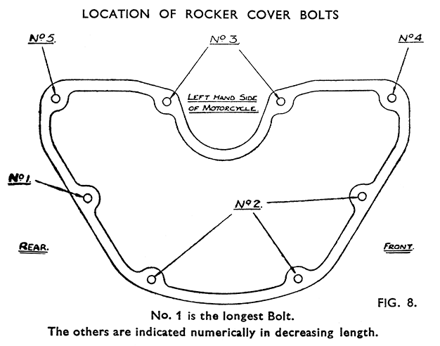
Remove the rocker cover. It is held by eight bolts of five different lengths—the positions they occupy should be noted for subsequent replacement (Fig. 8).
Should the cover not come clear easily, rotate the crankshaft until the inlet valve is full open. The front of the cover will then slide over towards the left of the machine and the rear edge can be tipped over the inlet rocker quite easily.
Take out the sparking plug. If this is found to be tight in the threads do not force it, but drip a little penetrating oil or paraffin round the body of the plug and allow time for this to percolate between the plug and the head.
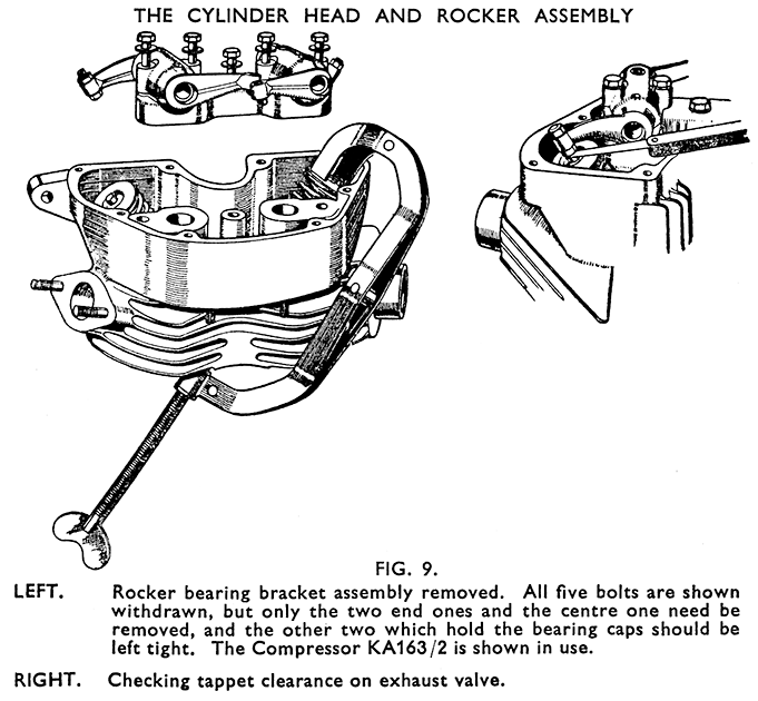
Rotate the crankshaft until both valves are seen to be closed. Take out the two bolts at the ends of the rocker bearing bracket and the one in the centre. Do not undo the other two - these hold the bearing caps. (Fig. 9).
Lift off the rocker bearing bracket assembly and rockers, and remove the gasket from the platform on the head. Lift out both push rods and mark them for replacement in the same positions. Do not interchange them.
Unscrew and remove the four cylinder head nuts and washers. Two nuts are outside the rocker box on the left, the other two down inside the cavities in the rocker bearing bracket platform.
Take off the nuts and washers from the flange studs of the upper push rod cover, and telescope the tube into the lower one. Keep the two gaskets and the guide plate for reassembly later.
Unscrew and lift out the four long cylinder studs from the cylinder base studs.
Remove the cylinder head - preserving the copper gasket for refitting. Removing Valves.
Compress the valve springs with the compressor tool KA163/2 (Fig. 9), and pick out the cotter. Keep the halves of each cotter together and do not interchange them or the valves and springs.
Refacing Valves.
The valves should be refaced on a valve refacing machine - the seat angle is 45°. This reduces the amount of grinding-in needed and saves unnecessary wear on the seatings in the head. Also clean up and polish the valve head but be careful not to reduce the diameter of the stem. The scale which may be found on the exhaust valve due to additives in the fuel, is often very hard, but can usually be cleaned off by holding a piece of carborundum against the scaled surface whilst the valve is rotated rapidly in a lathe or drilling machine.
Grind in each valve to its own seating using "fine" grade com-pound. Grind in only enough to give an uninterrupted matt grey surface all round the seatings on the valve and in the head.
Reconditioning the Cylinder Head Valve Seats.
As the valve seating material is very hard and durable, the seatings seldom need any other truing up than can be given by grinding in the valves, and they cannot be recut with the normal type of seating cutter.
After prolonged use and when refacing is needed they must be trued-up by grinding with a 45° valve seat refacing stone. Special equipment for this purpose is obtainable from various machine tool manufacturers.
Cleaning off Carbon Deposit.
Use only brass or copper scrapers on the piston crown and combustion chamber to avoid scratching the surfaces. The ports in the head may be cleaned by using emery cloth. Do not remove the ring of carbon which will have formed round the top of the cylinder bore.
After cleaning the piston crown rotate the crankshaft to bring the piston down the bore and clean off all carbon dust from the bore. After cleaning thoroughly bring the piston back to the top.
Replacement of Valve Guides. (Fig. 10.)
The valve guides are bored to allow diametrical clearances from the valve stems of .00125-in. to .0025-in. and are fitted during manufacture to the head when the head is heated.
Removal of worn guides for replacement purposes must not be attempted unless the metal of the head around the guides is heated up before pressing them out. The temperature should not exceed 100° Centigrade (boiling point of water). Immersion of the head in boiling water is a suitable means of heating, or the metal round the guide may be heated with a blow lamp provided the flame is moved about and not concentrated on one spot.
The head must also be heated before fitting new guides, which are pressed in leaving 5/8-in. protruding beyond the machined surface around the valve guide hole (Fig. 10).
After fitting new guides the valve seatings must be lightly trued up concentric with the guide bores, and the valves ground in.
Refitting Valves and Springs.
Place the valve spring bottom washers over the valve guides, concave side up, fit the springs with top collars. Lubricate the valve stems and push the valves into place and through the top collars. Compress the springs with the compresser KA163/2 and fit the cotters.
These may be stuck to the stem with grease to hold them whilst the compressor is released. After removing the compressor depress each valve smartly once or twice to seat it properly. The head is ready for refitting.
Refitting the Cylinder Head.
Inspect and if necessary renew the cylinder head gasket. Place the cylinder head in position and thread in the four long cylinder holding studs, screwing these into the cylinder base studs. Fit the cylinder head nut washers and nuts. Tighten down each nut a little at a time working from the first nut to the one diagonally opposite, and then doing the same with the other two, working round the head until they are all tight. Caution: The tension on the studs increases when the cylinder and head heat up and overtightening in the first place will cause damage.
Replacing the Overhead Rockers.
Refit the two gaskets with the push-rod guide plate between them on the flange of the push-rod cover, and fit and tighten the two nuts. It is most important not to omit the guide plate. Thread the push rods into position observing that they go back as marked during dismantling. If the piston is not already at top dead centre of the compression stroke, turn the crankshaft forward with a finger resting on each push rod. Observe the inlet one (nearer the cylinder) lift and fall, and as it reaches its lowest point the piston will be rising on the compression stroke. Bring it to the top.
Stick the rocker bearing assembly gasket, or a new one, in place on the platform and fit the bracket assembly and rockers, engaging the rocker tips with the cups on the push rods. Also check that the lower extremities of the push rods are seated correctly in the ball cups in the bottom rockers. Tighten the bearing assembly bolts evenly.
Readjusting the Tappets.
The clearances must be checked and set when the engine is cold. The running clearances, as distinct from the clearances used when checking the valve timing, are .005-in. on both valves.
Before checking or setting, the crankshaft must be turned so that the heel of the bottom rocker of the valve being dealt with is resting as nearly as possible midway on the neutral of the cam.Thus, when checking or setting the inlet tappet the exhaust valve must be just opening and when dealing with the exhaust clearance the inlet valve must be just on the point of closing.
Clearance is varied by turning the adjustable tappet in the rocker end after slackening the lock nut. One turn of the tappet will alter the clearance about .038-in. After adjustment retighten the locknut and check again.
Refitting Rocker Cover.
Clean both joint faces, stick a new gasket to the face of the head and fit the cover into place. Screw in the eight bolts having previously placed the lock washers over them. Note the positions occupied by the different length bolts (Fig. 8, page 23). Tighten carefully. Refit the rocker oil feed pipe, being careful not to overtighten and shear off the banjo bolt.
The remainder of the work calls for no special mention, except that before fitting, the threads of the sparking plug should be smeared with a little "Oil Dag", or graphite grease. For sparking plug recommendations, and instructions for cleaning and adjusting see page 65.


