- Details
- Category: MAC Instruction Book
- Hits: 1175
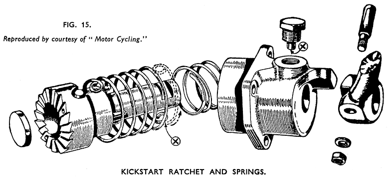
Dismantling Kickstart Ratchet and Spring. (Fig. 15.)
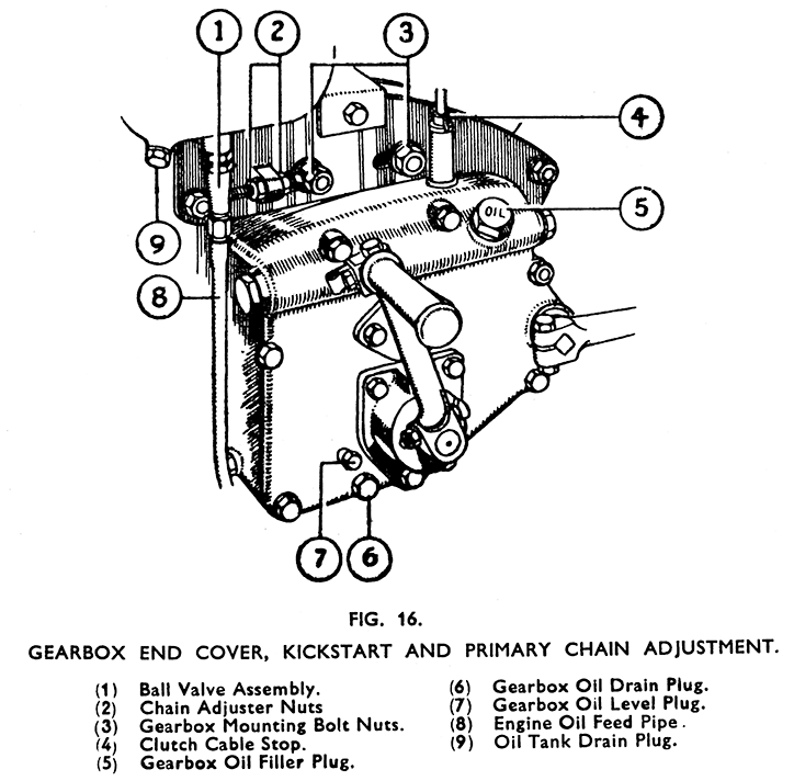
Drain the oil from the gearbox by removing the plug from the end cover (Fig. 16). Take out the three bolts holding the kickstart bearing to the end cover and draw it out of position with the ratchet, and kickstart crank, etc. Preserve the layshaft thrust washer from inside the ratchet.
Should the spring be broken the kickstart crank cotter may be removed at once, but if not the bearing and ratchet have to be held against the tension of the spring whilst driving out the cotter.
Remove the cotter nut and washer. Obtain two 2-in nails of small enough diameter to enter the breather holes in the ratchet. Knock these into the bench 1 19/32 -in. (1.593-in.) apart, or into a piece of wood held in the vice. Cut off the heads leaving about ½-in protruding from the surface of the wood.
Place the kick-start assembly, with the ratchet teeth downwards over the nails, entering the nails into the breather holes. Turn the kickstart bearing in a clockwise direction against the spring sufficiently to allow the head of the cotter to clear the disengaging ramp on the bearing. Drive out the cotter and gradually release the bearing.
If the spring is broken the ratchet will pull out of the bearing when the crank is tapped off. If unbroken tap the ratchet through far enough to expose the loop of the spring where this is fitted to the ratchet. Unhook the spring from its mounting and pull the ratchet out.
Note that the ratchet carries three thrust pins, 3/16-in dia. x 9/16-in long (.187-in. x .5625-in.) which must be preserved for refitting. These must not be confused with the three clutch thrust pins which are much shorter,
Take out the engaging spring which will be loose inside the kickstart bearing. Unscrew the kickstart spring anchor peg and remove the return spring - or the part of it if broken.
Replacement of Kick-start Spring. (Fig. 15.)
Push the end of the spring with the smaller loop (X) into the mouth of the kickstart bearing and by twisting the spring clockwise whilst holding the bearing firmly it will be found possible to work round the spring coil by coil and get it into place. In its free state the outside diameter of the spring is greater than the internal diameter of the kickstart bearing, but by twisting it round as described the coils will be compressed and will enter easily.
Leave the end of the spring with the larger loop, and one coil protruding, and manoeuvre the smaller loop in the kickstart bearing under the hole which carries the anchor peg and screw the peg home with its tip (X) through the spring loop.
Fit the three thrust pins into the ratchet. There are six holes, but the three which act as breather holes are slightly smaller than the others. Note specially that the correct thrust pins must be used. These are 3/16-in x 9/16-in. and are the same part as the big-end rollers. Discarded big-end rollers may be used as replacements. Do not, however, confuse them with the clutch thrust pins which are only .453-in. long. Stick them in place with a little grease.
Fit the engaging spring over the ratchet and push the ratchet into the kickstart bearing, engaging the loop of the spring (that was left protruding) over the anchor lug, that is formed on the ratchet.
Twist the ratchet round clockwise and push it further into the bearing at the same time entering the spring.
Place the ratchet over the two nails that were used in dismantling and fit the kickstart crank over the end of the ratchet.
Turn the housing round clockwise just far enough to allow the cotter to go through the crank across the flat on the ratchet. It fits from front to back. Do not in any circumstances turn the housing further than is needed to fit the cotter. Any extra tensioning of the spring will permanently distort and damage it.
Refitting Kickstart Assembly. (Fig. 15.)
Before fitting the assembly to the gearbox see that the layshaft washer is in place against the ratchet gear, the kickstarter bearing bush on the end of the layshaft, and the kickstart layshaft thrust washer in the ratchet.
Do not use a gasket between the face of the kickstart bearing and the gearbox end cover. Tighten the three bolts fully. Refill the gearbox.
- Details
- Category: MAC Instruction Book
- Hits: 1178
Removal of Front Half.
Proceed as described in the preceding section to remove the dynamo belt, but do not take out the dynamo clamp bolt. Remove the front part of the rear chain cover to expose the rear chain driving sprocket. Remove the split cotters from this sprocket and from the shock absorber collar nut. Drain the primary cover.
With the rear brake held on; loosen and remove the sprocket nut and the shock absorber collar nut, using spanner A61/2AS for the former and A229 for the latter. Preserve the plain washers which are fitted behind these nuts. The driving pulley, and pulley flange will come off with the collar nut. Remove the shock absorber spring and shock absorber clutch from the engine shaft.
The rear half of the belt cover can be raised over the engine shaft and the cover swung round out of the way of the primary cover.
Unscrew the primary chain cover strap fixing pin (3), Fig. 7, page 21, from the lug on the strap. Free the strap from the cover all round and push it off and over the back half of the cover. Remove the chain case fixing bolt (5) with washer and inner distance piece and pull out the joint mould¬ing.
Remove the cover. Preserve the distance tube fitted between the halves of the cover, and the felt oil seal around the opening for the clutch spring holder.
Removal of Primary Chain.
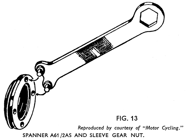
Fix the sprockets to prevent them turning by mounting a sprag from the bottom of the engine sprocket to the top of the clutch chain wheel. Take off the sleeve gear nut locking plate, held to the sleeve gear nut by a i-in. Whit. screw, and unscrew the sleeve gear nut, using the pegged end of the spanner A61/2AS. It will have to be started by driving it round, using a mallet on the spanner (Fig. 13).
As the chain is endless the engine sprocket and clutch assembly have to be drawn off their respective shafts together. The clutch may have to be levered off to start it by using levers carefully between the clutch back plate and the chain case. If care is taken to hold the clutch front plate and back-plate firmly together the clutch can then be refitted afterwards without it having been separated, unless of course it needs attention. Preserve the three thrust pins from the clutch back plate.
Removal of Rear Half of the Primary Chain Cover.
Having removed the clutch, the clutch thrust bearing is accessible, and the four screws securing the half cover to the gearbox can be taken out after cutting and drawing out the locking wires from the screw heads.
A gasket is fitted between the cover and the gearbox, and an oil seal ring between the cover and crankcase.
Refitting the Rear Half.
Verify that the chain case oil seal is in good order and in place on the crankcase main bearing boss. Stick the gasket - or a new one if needed - to the face of the gearbox with grease, and mount the chain case back half in place. Insert the four fixing screws and tighten fully. Fit new locking wires and twist the ends round securely to lock them. Use two lengths of wire passed through the screws horizontally. Do not wire upper to lower screws as this will interfere with the working of the thrust cup.
Refitting Primary Chain.
Engage top gear to prevent the sleeve gear slipping through its ballrace as the clutch is fitted. Verify the condition of the clutch thrust bearing, grease well, and replace, and see that the sleeve gear distance piece is in place on the sleeve gear and fitted through the thrust bearing.
Take up the clutch assembly, holding the back and front plates firmly together and stick the three thrust pins with grease into the holes in the clutch back plate. These pins are each 3/16-in. dia. x .453-in., and must not be confused with the thrust pins used in the kickstart ratchet - so that if this also has been dismantled the point should be checked.
Hang the chain over the clutch chain wheel, and rest the engine sprocket in the loop. The clutch assembly and engine sprocket with the chain in place have now to be placed on their respective shafts. Care is necessary not to allow the clutch plates to separate, and assistance is desirable for this part of the work.
Refitting the Sleeve Gear Nut.
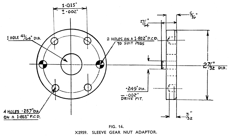
In order easily to refit the sleeve gear nut, which sometimes makes it necessary to compress the clutch spring slightly, the use of Service Tool X2959 sleeve gear nut adaptor (Fig. 14) is advisable. This is fitted over the gearshaft with the pegs engaged in the holes in the sleeve gear nut and the gear shaft nut used to compress the springs enough to start the sleeve gear nut on the thread. The four holes in the adaptor are to enable the peg spanner A61/2AS to be used to turn it.
After starting the sleeve gear nut on the threads, and having fitted the shock absorber clutch, spring, pulley, washer, and shock absorber collar nut sprag the chain and tighten both the sleeve gear nut and the shock absorber collar nut fully, finally driving the spanners round with a mallet. Fit the split-pin to the engine shaft. Readjust the clutch. See page 30.
Refitting Front Half of Primary Chain Cover. (Fig. 7.)
Put the chain case sealing strap in place over the back of the rear half of the primary chain cover. Fit the oil seal felt into its housing inside the cover around the opening for the clutch spring holder.* Fit the front half into place setting it in line with the back half, locating the chain case bolt distance piece over the plunged in edges of the bolt holes in the covers, fit the bolt and washer (5) and tighten up.
Press the joint moulding into place round the edges of the two halves of the cover with the ends at the top, and see that the centre rib fits between the cover faces. Bring the sealing strap over from the back into place over the moulding and tighten the bolt (3).
The reassembly of the dynamo belt cover calls for no special mention. Refill the chain case with oil.
* A new felt must be soaked in oil or molten tallow before fitting.
- Details
- Category: MAC Instruction Book
- Hits: 1115
See Fig. 7. Remove the outer half of the cover by unbolting it from the back half and taking off the nut holding it to the primary chain case.
Disconnect the positive (+) leads from the rear (red) terminal of the battery. This is most important.
Remove the dynamo clamp bolt (1) and turn the dynamo carcase in its mounting to loosen the belt. Take off the belt.
Pull out the single pin plug from the socket which protrudes through the commutator cover. The cover is marked +B at this point. (Fig 34, page 68.)
Take out the two screws holding the voltage regulator base to the dynamo strap.
Pull the dynamo and the back half of the belt cover out to the left side of the machine from under the strap, at the same time leading the two cables connecting the regulator to the dynamo out between the crankcase and strap.
To take the back half of the cover off the dynamo, remove the armature nut and draw the belt pulley off the taper. If a claw extractor is used be careful not to break the flange of the pulley.
It is usually possible to remove the pulley, after taking off the nut, by supporting it from the back and delivering a light sharp blow on the end of the armature. Always use a soft punch to avoid harming the thread if this method is used.
- Details
- Category: MAC Instruction Book
- Hits: 1798
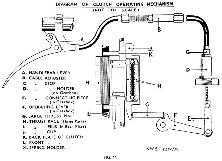
Description of Working. (Fig. 11.)
The clutch is operated by a thrust cup carrying a thrust bearing instead of by the more usual single thrust rod operating through a hollow gear shaft as on the LE model, and most other makes. The adjustment which becomes necessary periodically to allow for settling and wear on the friction linings is made by means of the screwed clutch spring holder threaded into the front plate of the clutch, and not by alteration to the cable adjustment. A cable adjuster is fitted, but this is used for controlling the cable adjustment only and must not be used as a "first aid" remedy for a slipping clutch.
Before attempting any adjustment to the clutch it is important that the operation of the clutch is properly understood and the following explanation should be studied by anyone unfamiliar with the design.
The operating mechanism is shown diagrammatically on page 27 (Fig. 11).
The movement of the handlebar lever (A) raises the operating lever (F) in the gearbox and the raised tip of the lever forces the large thrust pin(G) against the projecting lip of the thrust cup (J), causing the thrust cup to hinge outwards with the opposite side acting as the fulcrum.
If the outer clutch plate is observed whilst the handlebar lever is operated, with the clutch stationary, the plate will be seen to tilt outwards, as only that part of the plate nearest the thrust pin side of the clutch is freed from contact with the friction linings.
For the clutch to become fully disengaged the plates have to complete one revolution, after which the spherically seated, self-aligning ball thrust bearing (H) seated in the thrust cup levels the plates and frees them from the friction linings.
The disengagement of the front plate is arranged by the transmission of the outward movement of the thrust through the bearing (H) and three thrust pins (I) against the adjustable clutch spring holder (M) screwed into the front plate (L).
The thrust pins (I) are fitted freely in holes in the back plate (K).
Because of the tilting of the front plate the plates are " peeled off " from contact with each other so that when correctly adjusted and maintained this type of clutch does not cause the unpleasant grating of the gears on starting away which is often noticeable with other makes.
It will be understood that in normal use and a condition of correct adjustment the thrust pins and thrust bearing are free of all thrust loading. It will also be noted that settling or wear of the friction linings will allow the outer plate (L) to close in slightly towards the backplate (K) due to the reduction in friction lining thickness. As the thrust cup (J), when not in operation, is held against its seating and the face of the gearbox by a spring clip (not shown), it follows that the initial freedom in the thrust bearing and thrust pins will gradually be reduced, until a stage is reached in which, if adjustment is not carried when needed the thrust pins and bearing will be carrying part of the pressure of the clutch springs. The result will be clutch slip and premature wearing of the thrust bearing.
In such circumstances adjustment has to be made to the clutch spring holder (M) which must be turned forward (anti-clockwise) in relation to the front plate (L) to restore free movement in the thrust mechanism.
Adjustment of Clutch. (Fig. 12.)
Only in special circumstances, as described later, is adjustment of the clutch cable midway adjuster required.
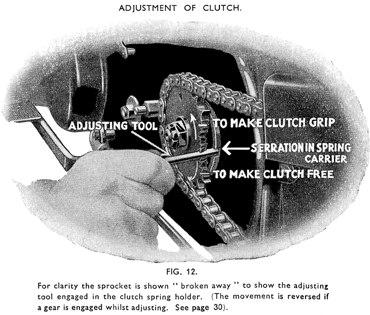
In the ordinary way the adjustment is made by turning the clutch spring holder in the clutch front plate by engaging the flat end of the adjusting tool KA62 /2 with one of the notches in the edge of the clutch spring holder through the ¼-in. hole in the final drive sprocket and moving the rear wheel in the direction required (Fig. 12).
To use the adjusting peg in the sprocket the front section of the rear chain guard has to be detached from the primary chain case. The chain guard is marked to indicate the need for its removal.
The adjustment is made normally with the gears in neutral, and only in an exceptional case is it made when an indirect gear is engaged. Such contingencies will be dealt with later.
To prevent clutch slip, i.e., to increase free movement in the operation, pull the rear wheel forward so that the final drive sprocket and adjusting tool will move the clutch spring holder forward in relation to the clutch front plate.
Should the clutch fail to free properly after this adjustment, the clutch cable adjustment may need a little correction : see next section.
Adjustment of Clutch on New Machines or after fitting New Cable Assembly.
The adjustment of the clutch is correct when a new machine is despatched from the factory, but the friction linings (clutch inserts) may settle during the first few hundred miles running, and readjustment may be needed fairly soon.
The clutch cable adjustment seldom needs attention after the initial compression and settling of the outer casings and ferrules of a new cable assembly has taken place. The control cable itself does not stretch, but very slight shortening of the total length of the casings may occur with new parts and has the same effect as a lengthened inner wire.
A careful watch should be kept on the clutch lever during the running in period of a new machine, if the clutch has been relined, or a new cable assembly has been fitted.
The settling down of the clutch inserts allows the clutch front plate to close in gradually towards the back plate and reduces the freedom allowed in the thrust bearing during assembly.
This in turn causes the control cable to lose some free movement. On the other hand any shortening of the control cable casings due to com¬pression will tend to hide the fact that the inserts have settled and clutch slip is possible even whilst there is still some lost motion in the cable.
It is recommended, therefore, that during the service check normally carried out after the first 500 miles running, the clutch adjustment should be dealt with by carrying out a series of operations, each very simple, exactly as described later and in the order given.
With the clutch in correct adjustment it must be possible to pull back the clutch lever quite freely, and without operating the clutch at all, far enough to move the inner wire (or clutch cable) ¼-in. to 3/8-in Should this free movement be seen to have decreased, re-adjustment must be made at once.
The sequence of operations for adjusting as mentioned previously is as follows :
Operation 1. - Slacken off the midway cable adjuster fully to allow the nipple to be detached from the handlebar lever and slip it out of the hole in the lever.
Operation 2. - Open both throttle and air controls fully. Select neutral position of the gears, and depress the kickstart against compression and test for clutch slip. If the clutch is felt to slip omit Operation 3 and carry on with Operation 4.
If no slip can be felt carry on with Operation 3.
Operation 3. - Using the clutch adjusting peg as already described, pull the rear wheel backwards a quarter of a turn at a time checking for clutch slip after each movement. This will involve taking out the adjusting peg from engagement with the clutch spring holder before each test. As soon as the clutch can be felt to slip (and only just slip), proceed with Operation 4.
Operation 4. - Refit the cable nipple to the handlebar lever. Readjust the midway adjuster until all lost motion is taken out of the cable and the lever is just drawn up against the lever bracket on the handlebar. Do not force the adjuster but only just remove all play. When correct tighten the cable adjuster locknut.
Finally, refit the adjusting peg to the sprocket, engage it with the clutch spring holder, and pull the rear wheel forward a little at a time until free movement begins to appear on the cable when the handlebar lever is checked.
Adjust until there is free travel on the cable of ¼-in. to 3/8-in.
The adjustment is now completed.
Although the foregoing may seem complicated at first sight the whole " drill " is both easily and quickly carried out, and after the initial settling of a new cable assembly has taken place is only likely to be needed in special circumstances, as for instance if it is not known whether adjust¬ment is needed to the cable or the spring holder. The effect of the two adjustments is inter-related.
If in doubt as to whether the cable or spring holder should be adjusted
the following should be referred to :-
Symptom : Clutch slipping. No lost motion on control cable.
Remedy : Readjust clutch spring holder forward.
Symptom : Clutch slipping. Lost motion present on control cable.*
Remedy : Carry out Operation 4 of Adjustment "drill."
Symptom : Clutch not freeing. Normal or excess lost motion on cable.
Remedy : Carry out full Adjustment " drill."
Symptom : Clutch slipping and also not freeing.*
Remedy : Carry out Operation 4 of Adjustment "drill."
It can be accepted that if clutch trouble is not eliminated by carrying out the " drill " exactly as described the clutch will have to be dismantled to attend to a mechanical fault, to rectify incorrect assembly, or to replace worn parts.
* See next section.
Adjusting a Tight Clutch Spring Holder.
If excessive slip through neglect of the adjustment, or a spring holder which is tight in the clutch front plate, causes the clutch front plate to move round with it when adjustment is attempted, the adjustment should be made in the following manner.
Engage either second or third gear, and after passing the adjusting peg through the sprocket, move the clutch by means of the kickstart until one of the notches in the spring holder is opposite the peg and engage the peg in the notch.
To make the clutch grip move the rear wheel backwards. This is the opposite direction to that used when adjusting with the gears in neutral.
By adjusting with an indirect gear engaged advantage is taken of the difference in the rates of movement of the clutch sleeve gear (to which the clutch driven plates are attached) and the final drive sprocket.
Oil in the Clutch.
The primary chain case is intended to carry enough oil to lubricate the chain, and the clutch will grip satisfactorily even if there is an excess of oil in the cover provided that from the outset the cover has had oil in it.
It has been found however, that a clutch which has been run completely free of oil over a period will be subject to slip if oil is subsequently introduced on to the friction surfaces. In such circumstances the clutch must be relined, and assembled with oil in the cover.
- Details
- Category: MAC Instruction Book
- Hits: 1137
The mileage that an engine will run efficiently without being decarbonised depends to a great extent upon driving conditions. A new engine is the better for receiving this attention after the first 2,000 to 3,000 miles have been covered. Afterwards it will probably be found to run perfectly satisfactorily for very much greater distances without similar attention. Whilst it is impossible to lay down any hard and fast rule it may be said that generally the average private owner does the work too often rather than too seldom.
If the engine is running well, and there is no noticeable loss of power, or other evidence such as a tendency to "pink" excessively it is best not to disturb it.
During the operation do not remove the cylinder barrel, unless there is good reason to do so. Removal means disturbing the piston rings, which can never be replaced in exactly the positions in which they have settled and bedded in to the cylinder and piston, and their frequent removal and reassembly may cause an increase in oil consumption.
Dismantling Cylinder Head.
Disconnect the petrol pipe from the tank. Take off the tank strap from beneath the front end of the tank. Pull off the sleeve connecting the carburetter to the air filter. Remove the fuel tank and take off the carburetter. Note that a special heat insulating gasket is used between the carburetter flange and the cylinder head.
Remove the silencer and the exhaust pipe together. Unscrew the banjo hollow bolt and the bottom union nut from the rocker oil pipe, and remove the pipe.
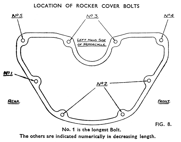
Remove the rocker cover. It is held by eight bolts of five different lengths—the positions they occupy should be noted for subsequent replacement (Fig. 8).
Should the cover not come clear easily, rotate the crankshaft until the inlet valve is full open. The front of the cover will then slide over towards the left of the machine and the rear edge can be tipped over the inlet rocker quite easily.
Take out the sparking plug. If this is found to be tight in the threads do not force it, but drip a little penetrating oil or paraffin round the body of the plug and allow time for this to percolate between the plug and the head.
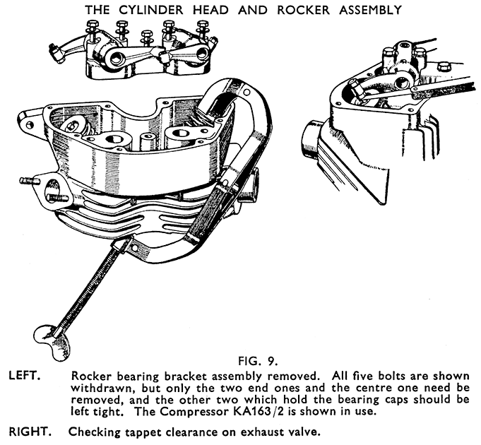
Rotate the crankshaft until both valves are seen to be closed. Take out the two bolts at the ends of the rocker bearing bracket and the one in the centre. Do not undo the other two - these hold the bearing caps. (Fig. 9).
Lift off the rocker bearing bracket assembly and rockers, and remove the gasket from the platform on the head. Lift out both push rods and mark them for replacement in the same positions. Do not interchange them.
Unscrew and remove the four cylinder head nuts and washers. Two nuts are outside the rocker box on the left, the other two down inside the cavities in the rocker bearing bracket platform.
Take off the nuts and washers from the flange studs of the upper push rod cover, and telescope the tube into the lower one. Keep the two gaskets and the guide plate for reassembly later.
Unscrew and lift out the four long cylinder studs from the cylinder base studs.
Remove the cylinder head - preserving the copper gasket for refitting. Removing Valves.
Compress the valve springs with the compressor tool KA163/2 (Fig. 9), and pick out the cotter. Keep the halves of each cotter together and do not interchange them or the valves and springs.
Refacing Valves.
The valves should be refaced on a valve refacing machine - the seat angle is 45°. This reduces the amount of grinding-in needed and saves unnecessary wear on the seatings in the head. Also clean up and polish the valve head but be careful not to reduce the diameter of the stem. The scale which may be found on the exhaust valve due to additives in the fuel, is often very hard, but can usually be cleaned off by holding a piece of carborundum against the scaled surface whilst the valve is rotated rapidly in a lathe or drilling machine.
Grind in each valve to its own seating using "fine" grade com-pound. Grind in only enough to give an uninterrupted matt grey surface all round the seatings on the valve and in the head.
Reconditioning the Cylinder Head Valve Seats.
As the valve seating material is very hard and durable, the seatings seldom need any other truing up than can be given by grinding in the valves, and they cannot be recut with the normal type of seating cutter.
After prolonged use and when refacing is needed they must be trued-up by grinding with a 45° valve seat refacing stone. Special equipment for this purpose is obtainable from various machine tool manufacturers.
Cleaning off Carbon Deposit.
Use only brass or copper scrapers on the piston crown and combustion chamber to avoid scratching the surfaces. The ports in the head may be cleaned by using emery cloth. Do not remove the ring of carbon which will have formed round the top of the cylinder bore.
After cleaning the piston crown rotate the crankshaft to bring the piston down the bore and clean off all carbon dust from the bore. After cleaning thoroughly bring the piston back to the top.
Replacement of Valve Guides. (Fig. 10.)
The valve guides are bored to allow diametrical clearances from the valve stems of .00125-in. to .0025-in. and are fitted during manufacture to the head when the head is heated.
Removal of worn guides for replacement purposes must not be attempted unless the metal of the head around the guides is heated up before pressing them out. The temperature should not exceed 100° Centigrade (boiling point of water). Immersion of the head in boiling water is a suitable means of heating, or the metal round the guide may be heated with a blow lamp provided the flame is moved about and not concentrated on one spot.
The head must also be heated before fitting new guides, which are pressed in leaving 5/8-in. protruding beyond the machined surface around the valve guide hole (Fig. 10).
After fitting new guides the valve seatings must be lightly trued up concentric with the guide bores, and the valves ground in.
Refitting Valves and Springs.
Place the valve spring bottom washers over the valve guides, concave side up, fit the springs with top collars. Lubricate the valve stems and push the valves into place and through the top collars. Compress the springs with the compresser KA163/2 and fit the cotters.
These may be stuck to the stem with grease to hold them whilst the compressor is released. After removing the compressor depress each valve smartly once or twice to seat it properly. The head is ready for refitting.
Refitting the Cylinder Head.
Inspect and if necessary renew the cylinder head gasket. Place the cylinder head in position and thread in the four long cylinder holding studs, screwing these into the cylinder base studs. Fit the cylinder head nut washers and nuts. Tighten down each nut a little at a time working from the first nut to the one diagonally opposite, and then doing the same with the other two, working round the head until they are all tight. Caution: The tension on the studs increases when the cylinder and head heat up and overtightening in the first place will cause damage.
Replacing the Overhead Rockers.
Refit the two gaskets with the push-rod guide plate between them on the flange of the push-rod cover, and fit and tighten the two nuts. It is most important not to omit the guide plate. Thread the push rods into position observing that they go back as marked during dismantling. If the piston is not already at top dead centre of the compression stroke, turn the crankshaft forward with a finger resting on each push rod. Observe the inlet one (nearer the cylinder) lift and fall, and as it reaches its lowest point the piston will be rising on the compression stroke. Bring it to the top.
Stick the rocker bearing assembly gasket, or a new one, in place on the platform and fit the bracket assembly and rockers, engaging the rocker tips with the cups on the push rods. Also check that the lower extremities of the push rods are seated correctly in the ball cups in the bottom rockers. Tighten the bearing assembly bolts evenly.
Readjusting the Tappets.
The clearances must be checked and set when the engine is cold. The running clearances, as distinct from the clearances used when checking the valve timing, are .005-in. on both valves.
Before checking or setting, the crankshaft must be turned so that the heel of the bottom rocker of the valve being dealt with is resting as nearly as possible midway on the neutral of the cam.Thus, when checking or setting the inlet tappet the exhaust valve must be just opening and when dealing with the exhaust clearance the inlet valve must be just on the point of closing.
Clearance is varied by turning the adjustable tappet in the rocker end after slackening the lock nut. One turn of the tappet will alter the clearance about .038-in. After adjustment retighten the locknut and check again.
Refitting Rocker Cover.
Clean both joint faces, stick a new gasket to the face of the head and fit the cover into place. Screw in the eight bolts having previously placed the lock washers over them. Note the positions occupied by the different length bolts (Fig. 8, page 23). Tighten carefully. Refit the rocker oil feed pipe, being careful not to overtighten and shear off the banjo bolt.
The remainder of the work calls for no special mention, except that before fitting, the threads of the sparking plug should be smeared with a little "Oil Dag", or graphite grease. For sparking plug recommendations, and instructions for cleaning and adjusting see page 65.


