- Details
- Category: F62-1R Service Manual
- Hits: 488
THE CRANK ASSEMBLY
Parting for attention to Big Ends.
The crank assembly is built up from five main components ; the driving shaft and balance weight, the centre crank disc, the flywheel shaft and balance weight, and two crankpins. The balance weights and crankdisc are pressed on to the tapered ends of the crankpins.
The most convenient method of parting the assembly is to press the crankpins out of the balance weights leaving them for the time being fixed in the centre disc. Before parting mark the disc to indicate front and rear faces.
They can be pressed out of the balance weights on a Crankshaft assembly Tool No. LET807, using the plate LET910 with it, on a small hand press. (Fig. 27).
If the crankpins need renewing they can be pressed out of the centre disc. The disc can be rested on the fixture LET807 for the purpose or on the bed of the press if it is true.
Service rebushed connecting rods can be obtained from the Service Department, Hall Green, or from Velocette Dealers, in exchange for the worn ones, on payment of the bushing charge plus postage. If required to fit the original crankpins they should be ordered on 'low limit ' to compensate for the wear on the pins.
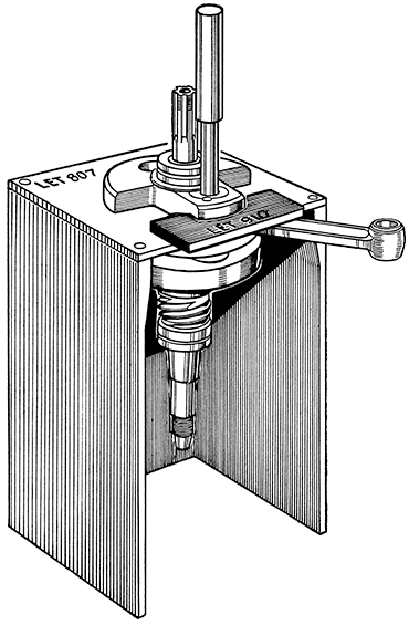
Fig. 27
Crankshaft Assembly Tool No. LET 807, and Assembly Tool Plate No. LET 910.
Crankshaft shown in position for pressing crankpin out of balance weight.
Special equipment is necessary to rebush the connecting rods. The bearings are in two halves and to fit them satisfactorily the Bushing Fixture LEF1267*, which first contracts the bearings and ensures that they enter the big end eye quite square, must be used. No reaming is required.
The small end bushes can be pressed out and renewed without special tackle. The bush must however be central with the big end. To check for lateral setting note that each side face must stand out .174-in. from the side face of the big end eye.
Ream the small end bushes to .5-in. +.00025-in. on reaming fixture LEF1248 (Not illustrated. Drawings can be supplied on application to Service Dept.)
Renewal will be necessary if the pins are worn unevenly or oval. To remove them support the crankdisc on the bed of the press or on the fixture LET807 with the pin that is to be pressed out directly under the ram, and below the disc. The front crankpin presses out away from the front face of the disc, and the rear one away from the rear face.
When placing new crankpins into position in the crankdisc prior to pressing them home note very carefully that the oil hole drilled radially through the taper must match up for the full width with the corresponding oil hole in the taper of the balance weight into which it will be fitted later. To ensure this check before fitting them to the disc that with the latter in such a position that the crankpin holes are at 12 o'clock and 6'oclock respectively, the oil holes in the crankpin tapers face exactly towards each other. In other words the oil hole in the upper pin will be at 6 o'clock and that in the lower one at 12 o'clock. Each pin goes in with the shoulder towards the recess.
Failure to set the crankpins accurately at this stage will prevent the oil holes registering when the pins are pressed into the balance weights and the oil supply to the big ends will be reduced or even cut off altogether.
With the crankpins fitted correctly to the disc press them home up to the shoulders.
Fit the connecting rods, being careful to place the little end oil holes facing the crankdisc. Fit the balance weights over the tapers, but do not press home until the assembly has been lined up.
With the crankpins pushed into the tapers as far as they will go by hand line up both balance weights with the centre disc and with one another. Use a straight edge across the ground peripheries of the three components and set them as true as possible. Press the balance weights home up to the shoulders of the pins. Check the alignment of the assembly with a dial gauge, resting the main journals in V blocks, or by holding the shafts between centres. If using V blocks these must be firmly fixed to a base plate. The journals, bob weights, and centre disc must run within .001-in. of full accuracy. Tap the balance weights sharply with a lead or copper hammer to correct the alignment as required.
If the shafts run true, but the centre disc is eccentric, the cause is likely to be the balance weights pressed on slightly askew. Correct by striking the weight at the point required to bring the components co-axial.
Fitting New Mainshaft Bearings.
The crank assembly is supported in four bushes of which only one is in the crankcase. Of the remainder two are fitted to the flywheel housing, and one in the reduction gear steady plate. After fitting the bushes are line-reamed with the flywheel housing bolted to the crankcase. Some special equipment is therefore essential if a full rebushing job is undertaken.
Two fixtures LEF1233, and LEF1327 are required for reaming and bushing respectively. They are not normally supplied from the factory, but full working drawings of them can be supplied on application from which they can be made. A simple mandrel, with sleeve, and recessed plate (Fig. 28) and the Bushing Fixture LEF1386 will complete the equipment required (Fig. 29). These can be made quite easily from the details given in the two illustrations.
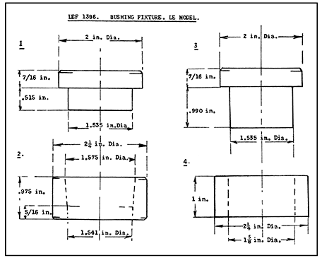
Fig. 28 Mandrel, Sleeve, and Plate for removal of and refitting bushes.

Fig. 29 LEF1386
The Flywheel Housing Bushes are removed by supporting the housing centrally on the sleeve 'B' (Fig. 28) front end downwards. Insert the recessed plate 'C' through the upper¬most (rear) bush and turn it to locate the recessed side in the lower (front) bush. With a bar of suitable size fitted through the upper (rear) bush press the lower (front) bush out of the housing into the sleeve 'B' .
The oil feed union must be unscrewed and taken out before attempting to press out the remaining bush which is carried in a separate housing pressed into the flywheel housing.
Invert the flywheel housing and rest the bearing housing centrally upon the sleeve 'B'. Thread the mandrel 'A' through the upper end and locate it in the bush. Press out the bush.
Rebushing the Flywheel Housing.
Place a new front end flywheel housing bush into the large end of the taper collar '2' of Fixture LEF1386 (Fig. 29). Rest the collar on the sleeve '4' and press the bush through the collar with the shorter mandrel '1'. Support the flywheel housing, front end uppermost, on a firm flat base, enter the bush into the front housing and press it home up to the shoulder, using mandrel '3'.
Compress the second bush, the longer of the two, in the collar '2' by pressing it into the collar with the shorter mandrel '1' in the same manner as the front bush was dealt with. Rest the flywheel housing front end on the sleeve '4' and enter the bush into the bush housing. Press in the bush using the mandrel '3' until the edge of the bush is just flush with the lower (front) face of the bush housing - that is the face remote from the end at which the bush enters.
When this bush is in place drill the oil hole (3/32-in. dia.) in the bush using the existing oil hole in the steel bush housing as a guide.
Unscrew and remove the rear main bearing oil feed union. Note that the crankshaft bush is drilled top and bottom to provide a feed to the camshaft bearings through a drilling in the back wall of the crankcase. After removing the old bush make absolutely sure that the drillings are quite clear and unrestricted.
Support the crankcase, rear end downwards, upon the mandrel 'A' locating the rear bush housing centrally on it. Insert mandrel 'A' through the front opening of the case and press out the bush.
As the oil hole for the camshaft feed cannot be drilled when the bush is in position drill the bush before fitting it, marking off the position from the old bush.
Use the fixture LEF1386 to compress the bush as before, but before pressing the bush into place mark the back face of the bearing housing and the face of the taper collar to show the exact position of the hole. Place the collar with the markings registered and the bush entered into the housing and press home. The bush must not stand proud of the housing faces back or front.
Check that the oil hole lines up with the camshaft oilway by passing a wire (1/16-in. dia.) through the hole in the bush and housing. Additionally insert the nozzle of a force feed oil can or syringe and force oil through until it is seen to issue from the hole in the camshaft bush.
Finally drill the bottom oil feed hole using the existing hole in the crankcase as a guide.
Line Reaming Crankshaft Bushes.
Fit the flywheel housing to the crankcase and tighten up the six ¼-in. B.S.F. nuts to secure it. Bolt the front and rear guide plates of Fixture LEF1233 to the housing front face and crankcase rear face respectively.
Enter the reamer through the guide hole in the front plate and, with the reamer piloted in the rear plate ream out all three bushes.
Blow out all oil holes, drillways, and passages with a powerful com¬pressed air jet, or paraffin from a pressure washer to clear off all swarf, dirt, or cuttings. Check that all passages, etc., are unrestricted. This is particularly important as engine failure will result if oil is prevented from reaching the bearings. Dry off all parts carefully using clean cloth that will not leave lint adhering to the metal.
The Reduction Gear Plate Bearings.
The fourth bearing that supports the crankshaft in the reduction gear plate should be inspected for wear. If due for renewal it is recommended that the plate assembly be exchanged for a service reconditioned one. Alignment of the plate with the crankcase is assured by the dowel used on the stud located top left of the timing gear pinion.
As it is not expected that rebushing will be necessary within the reason able life of the machine details are omitted from this publication. Should reference to it be found necessary the directions will be added to subsequent editions.
Verify that the camshaft oil feed drillway is clear as already described. Clean the shaft and bushes, oil the journals and enter the shaft from the rear end.
Clean off all parts, oil the rear journal and thread the assembly through the front of the crankcase, guiding the connecting rods through the accommodation slots (Fig. 26). Enter the rear journal into the crankcase bush and bring out the connecting rods through their respective cylinder openings. Oil the front journals, and place a gasket over the studs in the front face. Fit the housing over the studs, entering the journals in the bushes and setting the oil pump face at the bottom.
Fit the lock-washers and nuts and tighten evenly, each a little at a time, checking the crank assembly meanwhile for freedom of rotation.
Fit the outer thrust washer over the splined driving shaft, chamfered end to the front (inwards). Push the timing pinion up the splines, set the camshaft gear with the timing mark downward (Fig. 30) and with the timing pinion located on the key bring the marks into register. When correctly located press it home with Service Tool LET915 (Fig. 31).
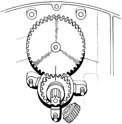
Fig. 30
Mesh the timing gears by the etched marks.
Fit the reduction gear pinion with the
reduced face towards the driving shaft collar.
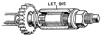
Fig. 31 Service Tool No. LET 915 pressing timing pinion on driving shaft.
Refitting the Reduction Gear Plate Assembly.
Fit the dowel to the counterbored stud hole (top left of timing pinion). As there is sometimes difficulty in getting the reduction gear oil pipe banjo bolt in place after the plate is fitted it is advisable to place the pipe in position, and fit the hollow bolt through the double banjo and into the plate before the latter is located on the studs. Do not omit the copper banjo gaskets. Check all oil holes in the plate.
Oil the bearing collar on the pinion and fit the plate over it and on to the dowel and studs. Push the two upper bolts through the plate and crankcase and fit the special locknuts on the outside. Do not interchange standard B.S.F. nuts for them. Fit remaining nuts and lock-washers and tighten fully.
Check this as soon as the reduction gear plate has been fitted. It should be between .003-in. and .007-in. and is unlikely to be incorrect unless a new camshaft assembly and /or thrust button have been fitted.
To adjust the float alter the thickness of shimming behind the thrust button that is fitted to the reduction gear plate. Shims are supplied in three thicknesses : .003-in., .005-in., .008-in. Aim to get as near .004-in. float as possible.
Refitting Reduction Gear Pinion.
Push the pinion on to the splines noting that the reduced diameter face goes against the timing pinion (Fig. 30).
Fit the tab washer and lock-ring. Chock the rear balance weight with a piece of wood (Fig. 24) and tighten the lock-ring fully. Give the spanner one or two blows with a hammer to ensure security, but do not use exces¬sive force. Bend a tab of the washer into a serration in the lock-ring. Remove the wood block.
The Flywheel Housing. Oil Seal.
Note that irrespective of the type, a new oil seal can be fitted without dismantling any further than the removal of the generator stator plate and the flywheel.
On early engines it is carried in a separate steel housing held to the front of the flywheel housing by three 2 B.A. bolts (Fig. 32). For these engines the oil seal can be obtained ready fitted to the steel housing which is then attached to the casting and centralised by using Service Tool LET793. A gasket fits on the joint face, and it is advisable to coat both sides with a good jointing compound (Gasket Goo). Note that behind the oil seal there is a small drain hole to carry oil from the bush back to the sump. See that this is clear of restriction by inserting a piece of wire, and when applying the jointing compound do so with care so that none gets into the oil hole.
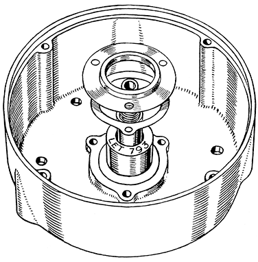
Fig. 32 The Flywheel Housing Oil Seal is centralised by the use of Tool LET793.
Engines from No. V200/1208 have the oil seal pressed into the flywheel housing direct. In the case of this type tap the seal carefully and square into the housing so that the flat face is flush with the front face of the housing, using the Service Tool LET1148 over the centralizing tool.
The flywheel must be set correctly in relation to the crankshaft. The setting is best accomplished by using Service Tools LET952 and LET1138.
Clean the flywheel boss and the internal taper. Make certain that the boss or collar at the back that runs in the oil seal is undamaged. If bruised, marked, or even scratched it will be impossible to prevent oil leakage past the seal. If it is necessary to true it up or polish it the collar diameter must in no circumstances be reduced below 1.245-in.
See that no particles of iron or steel are adhering to the magnets, oil the collar, and after seeing that the shaft taper is quite clean push the wheel on to the taper. N.B. - Unless the faces of the nut and distance piece are true any oil that leaks along the extension of the keyway in the taper may leak past them. The condition of the faces should therefore be verified before fitting. A little jointing compound can be used on them if desired. Fit the distance piece and nut screwing the latter up just far enough to hold the wheel in place but still free to turn on the shaft.
If the assembly of the engine has not proceeded as far as the fitting of the pistons and cylinders, fit them to the left hand side, securing the cylinder firmly to the crankcase. Fit the setting plate LET952 over the right hand side and top stator plate fixing studs with the dowel facing the flywheel and approximately level with the right hand stud. Turn the flywheel and engage the dowel in the dowel hole in the flywheel rim. Temporarily fix the plate with nuts. Fix the setting block LET1138 to the cylinder head face with two ¼-in. B.S.F. bolts of suitable length and turn the crankshaft clockwise until the piston comes into contact with the setting block and stops further movement (Fig. 33).
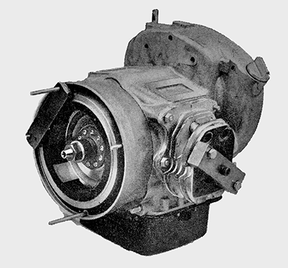
Fig. 33 Service tools LET952 and LET1138 in use.
Tighten the flywheel nut securely to hold it firmly on the taper, and when tight remove the setting plate and block.
It will be noted that when the pistons are at top dead centre, and the flywheel is correctly fitted, the dowel hole in the flywheel is co-axial with the hole in the top of the stator plate (Fig. 21). It is possible in case of necessity to use this for setting the flywheel relative to the shaft, but the special setting tools should always be used in preference to any other method.
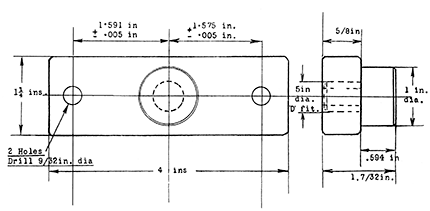
Fig. 34 Setting Block LET1138
If the special equipment is not on hand proceed as follows: Bring the pistons to top dead centre and push the flywheel lightly on to the taper, setting the dowel hole as nearly as possible at 12 o'clock'. Fit the stator plate and check the position of the dowel hole in relation to the hole in the plate. If the flywheel has to be moved insert a small peg through the hole and pull it round in the direction required, being careful not to move the crank. There is always a degree or so of movement of the flywheel at the dead centres that causes no noticeable movement of the pistons. Allow for this movement to occur from the centre of the ½-in. hole in the stator plate to the left (viewing the assembly from the front - Fig. 21.)
When set remove the stator plate very carefully, as the flywheel must not be moved on the taper, and fit the distance piece and nut (see note re faces of these above). Tighten the nut carefully and when secure fit the stator plate and check the setting of the flywheel again.
Refitting the Timing Unit and Retiming the Ignition.
The stator plate must be fitted. Clean the tapers of the shaft and unit and push the unit lightly up on to the shaft. Fit the centre fixing pin and tighten it carefully. Adjust the contact point gap to .015-in. fully open. This setting is critical and must be accurate otherwise the running will be affected. Having set the clearance remove the unit from the taper with the extractor bolt LET948 (Fig. 21). Remove the bolt from the unit and refit the latter lightly on the taper this time setting it so that the points just separate when the pistons are at top dead centre. This can be checked by means of the dowel hole in the flywheel. When the correct setting is achieved tighten the centre fixing bolt. Do not overtighten or use a spanner on the bolt head to turn the crank. Overtightening will expand the centre sleeve and will prevent the timing unit working.
The exact instant that the points separate can be checked by switching on the ignition and watching the ammeter. A discharge will be shown when the points are in contact, but the ammeter needle will flick back to centre as soon as they 'break'.

