- Details
- Category: F62-1R Service Manual
- Hits: 476
THE ENGINE ASSEMBLY
With the engine out of the frame and separated from the gearbox and clutch housing assemblies (see preceding sections) drain out the oil, and clean down externally of all excess road dirt. Remove the engine front support member. Remove the oil sump as it is easier to rest the engine on the bench without it.
Removal of Oil Pipes etc.
Fig. 20 Arrangement of Internal Oil Pipes
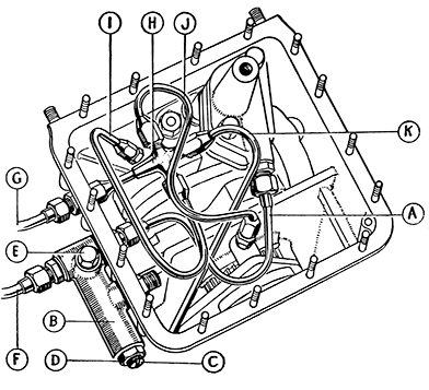
| A | Oil Pipe - Pump to Pressure Release Valve |
| B | Oil Pressure Release Valve Body. |
| C | Oil Pressure Adjusting Screw. |
| D | Oil Pressure Adjuster Lock-nut. |
| E | Oil Pressure Valve Body Bolt. |
| F | Oil Pipe - To Filter. |
| G | Oil Pipe—From Filter |
| H | Oil Distributor Block Assembly. |
| I | Oil Pipe—To Flywheel Shaft Bearings. |
| J | Oil Pipe—To Crankcase Bearing. |
| K | Oil Pipe—To Reduction Gear Plate. |
The filter will already have been removed when the gearbox was taken off. If the oil pipes leading to and from it were not removed then, take them off now. Disconnect all the internal oil pipes (Fig. 20) and unscrew the oil union to which pipe 'G' was attached by using a spanner on the hexagon and at the same time holding the hexagon of the distributor block assembly from turning. Take out the distributor when free. The oil pump is held by a barrel nut to the flywheel housing. It can be removed at this stage, and will pull clear after the nut is taken off.
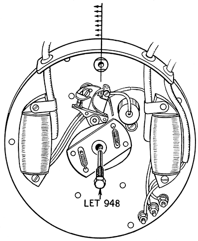
Fig.21 Resetting Miller Flywheel.
Dowel hole in flywheel is shown set central in relation
to hole in Stator Plate at top dead centre. The Timing Unit is shown in full retard position.
Note also Extractor Bolt Service Tool No. LET 948 for withdrawing timing unit.
Take off the large circular cover from the generator. Remove the bolt from the centre of the timing unit. The crank can be prevented from turning by ' chocking ' the front balance weight with a block of wood inserted between it and the inner wall of the case.
In place of the timing unit fixing bolt screw in the extractor LET 948 (Fig. 21). Tighten it until the unit is freed from the taper. Take away the unit and remove the extractor from it.
Removal of Stator Plate Assembly.
Remove the four 2 B.A. nuts securing it to the flywheel housing. If not already disconnected detach the generator leads at the jack connectors, and the ignition leads from the sparking plugs. Pull the stator plate assembly forward off the fixing studs exposing the flywheel.
The flywheel is carefully set during original assembly so that the pole pieces are in correct relation to those on the stator plate at the instant the contact points separate. If this setting is not correct the maximum intensity of spark will not be obtained when the generator is switched to the emergency start position. Special equipment has been designed to facilitate this setting and it is advisable to have it available before taking off the flywheel.
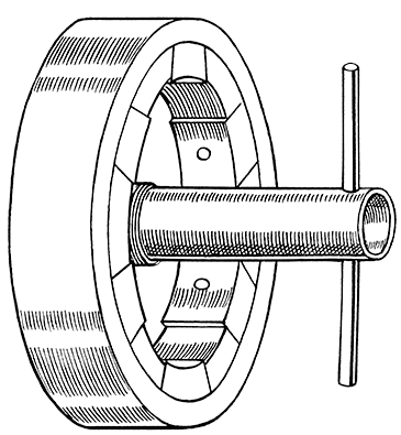
Fig. 22 Miller Flywheel Nut ½-in. Whitworth tubular spanner.
Chock the front balance weight as already described and undo the flywheel nut. A ½-in. Whitworth tube spanner will be required (Fig. 22). Pull off the distance piece behind the nut and screw the protector LET647 /1 on to the end of the shaft, and the extractor LET949 on to the flywheel threaded boss (Fig. 23). See that the crank is firmly 'chocked' and screw down the extractor screw until the flywheel is freed from the taper. If it is stubborn and will not part with reasonable pressure applied on the screw tap the flywheel very lightly indeed near the centre, using a soft metal punch to jarr it. Only the slightest vibration set up in this way will free a really firmly fixed wheel.
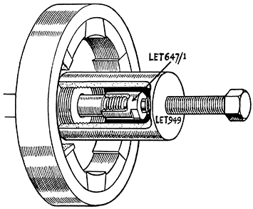
Fig. 23 Drawing Flywheel from Flywheel Shaft.
Illustration shows Service Tool No. LET949 for Miller Flywheel
Protector No. LET647/1 on end of shaft.
Remove the extractor from the flywheel and the protector from the shaft as soon as the flywheel is off, and store the flywheel away from all dirt and ferrous metal filings as these will become attracted to the powerful magnets.
If it is necessary to remove the flywheel without taking the engine out of the frame the crank can usually be held quite firmly from turning by engaging top gear before attempting to undo the flywheel nut. Alternatively the left hand side cylinder head can be taken off and the piston 'chocked'. Take great care if adopting either method not to derange the alignment of the crankshaft.
Removal of Reduction Gear Plate.
Stand the crankcase on the flywheel housing face. Chock the rear balance weight with a block of wood (Fig. 24) and unscrew the lockring after bending back the lockwasher tab. Use Service Tool LET780. The driving pinion will then draw off the splined end of the shaft.
In some cases the hollow bolt will not unscrew fully from the reduction gear plate before fouling the crankcase. It may therefore be necessary to defer the removal of the reduction gear oil pipe until the plate has been removed. The pipe, which also feeds the rocker gear, is attached to the crankcase at the top by another hollow bolt which must be taken out to free the pipe. Be sure to preserve the metal gaskets from the banjo unions.
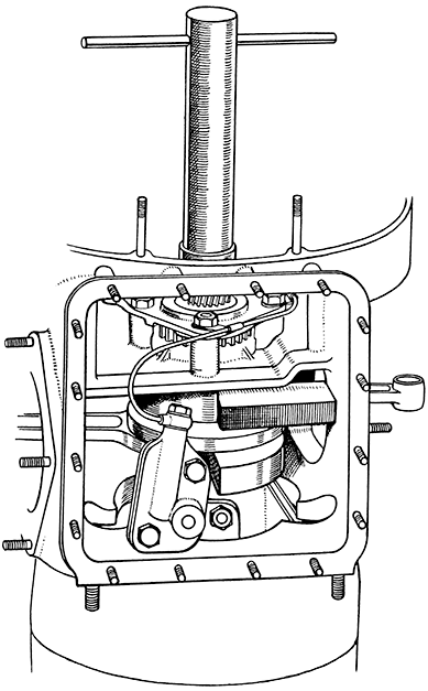
Fig. 24. Removal of Driving Shaft Lock Ring. Showing rear
bob-weight "chocked" with wood block.
Removal of Crankshaft Timing Pinion.
Draw the pinion from the shaft using the extractor LET802 (Fig. 25). Remove the wood chock from the crankshaft when the pinion is off. Also take away the hardened thrust washer from behind the pinion.
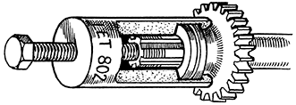
Fig. 25 Service Tool No. LET 802.
Extracting Timing Pinion from Driving Shaft.
Removal of Cylinders and Cylinder Heads.
Proceed as described previously under 'Decarbonising' page 14. Detach the rocker oil feed pipe assembly by removing the hollow bolt holding the double banjo to the top of the crankcase. Remove five cylinder base nuts from each cylinder and draw the cylinders off carefully and in line with the pistons. Careless removal may bend the connecting rods.
The tappets will come out freely from their guides. As they are taken out mark them, or note their respective positions so that when rebuilding the engine they all go back in their original places.
The gudgeon pins are retained by spring circlips, the removal of one per piston will allow the pin to be tapped out. To remove the circlip insert a sharp bradawl under the wire, using the groove cut for the purpose in the edge of the gudgeon pin hole. If no bradawl is at hand an old spoke ground or filed to a point will serve. In case the circlip springs out suddenly it is advisable to cover the piston with a piece of rag to prevent loss.
Tap out the gudgeon pin from the other side. Use a soft metal drift, and support the opposite side of the piston to stop the connecting rod taking any part of the pressure. If the pins will not move with light tapping heat the pistons to free them.
Unless new pistons are to be fitted, always mark the old ones to indicate from which side of the engine they were taken, and also to show which way up they were fitted. The piston skirt slot is underneath on the left and on top on the right.
Removal of Flywheel Housing Assembly. (After removal of Oil Pump.)
Remove the oil pump assembly first.
Take off six ¼-in. B.S.F. nuts, remove the lock-washers and pull the housing away from the front face of the crankcase. It may require light and careful tapping at several places to free the joint. Removal exposes the front end of the crankshaft.
Turn the crank to bring it into position to allow the small ends of the connecting rods to come through the extraction slots in the front wall of the crankcase. Pull the crank assembly forward out of the rear bearing, guiding the rods through the slots (Fig. 26).
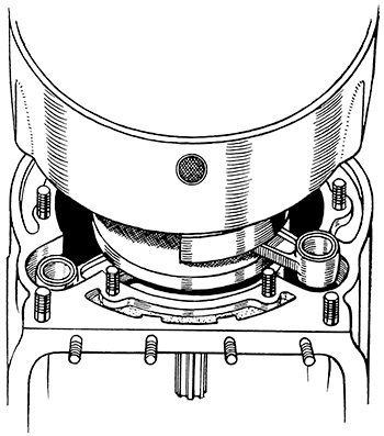
Fig. 26 Showing the slots through which the connecting rods must be guided.
After removal of the reduction gear plate the camshaft will draw out of the bearings towards the rear. The large gear and bearing boss are machined from one piece and pressed on to the shaft. Front and rear bearing bosses are then ground true with each other. The camshaft and timing gear are a single assembly the parts of which must not be separated.

