- Details
- Category: F62-1R Service Manual
- Hits: 650
THE CARBURETTERS.
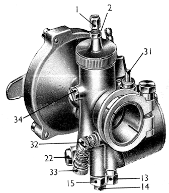
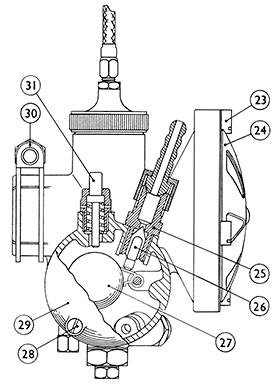
A carburetter atomises the correct amount of petrol with air that is forced into the engine by atmospheric pressure. A float chamber maintains a constant level of fuel at the jets and cuts off the supply when the engine stops. The float chamber is fitted with a tickler (31) for depressing the float to give a greater supply of petrol, should this be wanted, for starting the engine from cold. A filter strangler (24) on the main air intake provides for air regulation when starting a cold engine. A throttle valve operated by a cable from the handlebar controls the volume of mixture and there¬fore the engine power. At all openings of the throttle the mixture is automatically correct.
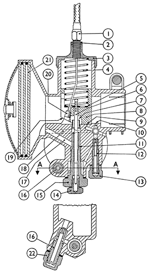
At small throttle openings, as for starting, idling, and slow running, a petrol /air mixture is taken into the port from the pilot system, fuel being fed via the main jet (16), through the pilot (12) where it mixes with air entering the pilot air passage (18), the resultant mixture then passing out of the pilot outlet (10) and pilot by-pass (9) where it mixes with air passing through the main air choke.
Further opening of the throttle then brings into action a petrol /air mixture from the primary air choke (7), fuel that has passed the main jet and needle jet mixing with air that enters via the primary air passage (17), and then discharging from the primary air choke (7), where it is intimately mixed with the main incoming air stream passing though the main air choke.
The cut-away (19) on the throttle valve influences the air passing through the main choke at this stage. In the earlier stages, that is up to three-quarters of throttle opening, the fuel supply for the mixture from the primary air choke is governed by the taper of the jet needle working in the needle jet. At later stages, that is three-quarters to full throttle, it is solely the size of the main jet that exercises the control.
Bleed holes (11) in the needle jet provide for an air compensating action in the mixture from the primary air choke, and fora well of fuel to form round the outside of the needle jet, this fuel being available for snap acceleration.

FIG. 48. A Type 363 Monobloc Carburetter.

Turn on the fuel supply at both taps. Set the throttle a ¼ to 1/3 open, fully close the left-hand strangler only (24). With the ignition switched off depress the starter a few times. Switch on the ignition and depress it again smartly. Open the strangler gradually and when the engine is running regularly throttle down to idling speed. If it begins to falter partly close the strangler again and until such time as it can be opened fully to the normal running position.
Leave the stranglers fully open. Set the throttle as when starting from cold.
Experience will show when it is necessary to use the strangler, and also the best setting of the throttle valves. If the carburetters have been flooded or over strangled, which will result in a ` wet engine and consequently over-rich starting mixture, open the throttle and stranglers fully, turn off the fuel, and give the engine several turns to clear the cylinders. Reset the throttle, leave the stranglers open and try to start again. Do not turn on the fuel until the engine starts. If the engine fails to start after this, take out the sparking plugs and dry them of surplus fuel. If the fault is thought to be in the carburetter, read and carry out instructions under ` Maintenance '.
Incorrect functioning of the carburetters may be the cause of : Engine refusing to start, or starting and cutting out, erratic running, continual sooting up of sparking plugs, poor acceleration, or loss of power, engine overheating or excessive fuel consumption. Check the setting and see that the carburetter is correctly adjusted.
The carburetters must be a good push fit on the induction stubs, and must be right home so that the gasket on each side is nipped between the intake of the carburetter and the end of the stub. Do not omit these gaskets when refitting carburetters. Tighten the clip securely (30). The gaskets between the stubs and the cylinder heads must also be in good condition and the stub nuts fully tightened.
Ensure that an ample supply is reaching each carburetter. Test by disconnecting each feed pipe in turn from the float chamber, and turning on the fuel tap to see if the flow is unrestricted.
Check that there is no continual flooding due to the float needle (26) sticking and not shutting correctly or being held off the seating by foreign matter on needle or seating. To clean, remove the three side cover screws (28) when the cover (29) float (27) and float needle (26) can be removed. Take care not to damage the joint faces of the side cover or float chamber. Flush out the chamber and needle seating (25) with clean petrol. Wipe clean and refit. Do not clean by scraping, etc. On old machines, flooding may be due to wear on the needle or seating, or a leaking float. Replacements should be fitted if necessary. When reassembling set the needle with the pointed end upwards, and see that the side cover gasket is in good order.
Main Jet and Pilot Jet. (16 & 12).
Check that they are not obstructed with foreign matter. To remove them; first remove their cover nuts (22 & 13). They can then be removed by means of a screwdriver. Clean by washing in clean petrol, and blow through their passage ways. A tyre inflator is useful for this if no com¬pressed air line is handy. Do not prod them with wire or anything that might enlarge the bores.
Screw in firmly after cleaning but do not use excessive force. If they are loose the mixture strength is upset. Refit the cap nuts.
Check that it is unobstructed. Unscrew it from the carburetter, and take out the plug screw (14). Clean as described for the other jets. On old machines the portion where the jet needle operates may be worn, thus enriching the mixture over the major range of the throttle opening. In cases of heavy fuel consumption this may be the cause and a new jet should he fitted.
Jet Needle and Throttle Valve (6 & 8).
Check that the throttle valve and needle move freely up and down when the control is operated. On old machines check that no undue wear has taken place between the throttle valve and the bore in which it works, and on that portion of the needle that operates in the needle jet. Renew if wear has taken place. The throttle valve with the needle and attached to the cable can be withdrawn from the carburetter after unscrewing the knurled mixing chamber cap (3). To separate the throttle valve and jet needle from the cable, release the cable at the twist grip and push the inner cable forward in the throttle valve until the nipple (20) clears the hole, then withdraw the cable through the slot in the valve passing the nipple through the hole at the extreme end of the slot.
On reassembling, pass the nipple through this hole via the inside of the valve. Make sure that the portion of the jet needle clip (5) that falls in towards the jet needle is opposite the cable slot in the valve, and then draw the nipple forward until it will pass over the end of the valve and settle into the hole.
When putting back the throttle valve assembly into the body, see that the locating screw in the body engages the key-way opposite the cable slot in the valve, and that the jet needle enters the needle jet before attempting to push it home.
Occasionally remove the elements for cleaning, and re-oiling. Take out the three screws (23), remove the shutter. Wash all parts in clean petrol. Dry off and then dip the elements in engine oil, allow to drain, and refit.
Check that there is no stoppage in any of the passages. It is seldom that foreign matter restricts them, but if so, the most likely places will be the pilot outlet (10) or pilot by-pass (9). To clear unscrew the pilot air bleed screw (32) until it is held by two or three threads only. It is helpful to note the exact number of turns that it is unscrewed so that it can be reset to the same adjustment after the work has been done. Remove the pilot jet cover nut (13) and jet (12). Blow through the passages with a compressed air jet or a tyre inflator.
Reassemble and reset the adjustment.
New machines are supplied with a standard setting of jets and throttle valve and there is nothing to be gained in any normal conditions by changing the jet sizes or valve. Only in extremes such as very high altitude working is any modification likely to be needed.
| The standard setting is: | Main jet | 100 |
| Pilot Jet | 15 | |
| Needle Position | No. 3 | |
| Throttle Valve | No. 2 |

FIG. 50. Sectional View Amal Monobloc Carburetter Type 363.
Remove both carburetters, and slack off the cable adjusters. Adjust the throttle valve stop screws to hold the throttle valves open grin. Check this setting by inserting a 1/32 -in. diameter (No. 68) drill, or a piece of wire under the valve. Refit the carburetters and readjust the control cable adjusters to give just 1/32-in. slack in each control cable.
Start the engine and run it until it is thoroughly warmed up.
Remove one sparking plug, replace it in the suppresser cover, and wedge the plug body against the fins so that the plug can spark. This avoids an open circuit.
Start the engine and adjust the pilot air screw until even running is obtained on the one cylinder. It is possible that the screw will have to be as much as four turns open.
Replace the sparking plug, and remove the one from the opposite cylinder. Repeat the procedure exactly.
Refit the sparking plug, and start up on both cylinders. The engine will now be found to run too fast, and the stop screws should be lowered one eighth of a turn at a time on alternate sides until the desired tick-over speed is obtained. Be careful to lower both screws the same amount so that the throttles are maintained "in step". Do not attempt to get a very slow tick-over.
In making the adjustments and checking as described above always make allowance for the fact that after the throttle is closed down and the engine slows down from higher speeds, there is a slight lag in the closing of the timing unit, and the ignition will not be fully retarded immediately. If this is not allowed for it may be thought that the stop screws have not been screwed down far enough, and they may thus be set so that the engine will stop when the fully retarded position is reached.
Occasionally difficulty in getting even idling may be caused by the throttle valves not closing freely due to the locating pegs in the sides of the mixing chambers "bottoming" in the grooves in the throttle valves. It is advisable therefore in case of difficulty to remove the throttle valves and polish the grooves to give free and smooth movement.
In the case of old machines where the needle jets and or jet needles are suspected of having worn enough to increase the fuel consumption, the replacement of the worn parts can sometimes be postponed by lowering the needles relative to the throttle valves. This is done by springing the needle clip off the needle, lowering the latter by one groove and refitting the clip in the next higher groove.

