- Details
- Category: F62-1R Service Manual
- Hits: 584
THE BEVEL DRIVE ASSEMBLY
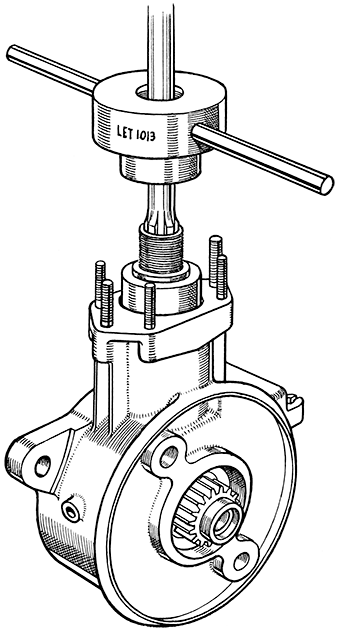
FIG. 39
LET1013 Muff Coupling Extractor (with collar in position).
Removal of Bevel Drive Casing.
Unless the swinging fork assembly is first taken out, which entails removal of the engine and gearbox, the quickest means of removing the bevel drive assembly for attention is to unbolt it from the rear flange of the fork casting. It is held to it by four ¼-in. and two 5/16-in. B.S.F. nuts. The rear suspension unit on this side and the brake cable must be detached.
After withdrawing the assembly from the fork flange it will be noted that the propeller shaft assembly and muff coupling which is a press fit on the bevel pinion splines will come away too bringing the spring with it.
Removal of Bevel Pinion Assembly.
If the bevel pinion, oil seal, or bearings are to be renewed the muff coupling and propeller shaft must be withdrawn from the splines. There is an extractor LET1013 for this operation (Fig. 39). The bevel pinion assembly with bearings and oil seal can however be withdrawn from the housing together with the propeller shaft if such replacements are not required.
Drain oil from the casing. Support the assembly in the vice (first covering the jaws). It must be held so that the vice jaws press against the ends of the fixed spindle. It is however preferable, if the entire assembly is to be stripped, to remove the bevel casing cover, spindle, and crown wheel shaft first and then hold the casing by securing it to a suitably drilled vice-plate (Fig. 40).
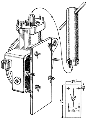
FIG. 40
A Vice Plate mounted as shown and held in the vice while using
Service spanner LET781 to remove bevel pinion lock ring.
With the casing held as shown extract the propeller shaft assembly, or if it is to be left attached to the pinion, proceed right away to unscrew the bevel pinion lock-ring using spanner LET781.
When it has been removed heat the bevel housing carefully around the neck and withdraw the pinion and the bearings with it. Any packing shims that are fitted between the pinion outer race and the casing must be taken out and preserved for refitting. The fitting of a new pinion may call for a greater or smaller number of shims, but the old ones can mostly be used again.
Although it is possible to renew the oil seal after drawing off the muff coupling, the bevel and bearings must be withdrawn from the casing for refitting the coupling. In no circumstances press back the coupling whilst the pinion is fitted to the casing. The 'head' of the pinion must be supported on the bed of the press when refitting them.
The oil seal and housing will pull off over the splines, and if a new seal has to be fitted press out the old one and fit the replacement using Service Tool LET 787 (Fig. 41).
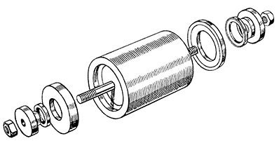
FIG. 41
Tool LET787 for the replacement of oil seals
Bend back the tabwasher from the pinion lock-ring. Fix the Vice tool LET788 in the rice (Fig. 40). Hold the spanner LET789 over it and insert the splined end of the pinion through the spanner and into the Vice tool. Engage the spanner with the lock-ring and unscrew it. Remove the lock-ring and tabwasher.
Place the bevel pinion outer race upon a suitable bush. Size 1½-in inside diameter, 2-in. outside diameter, and 2½-in long, and press the pinion out of the bearings (Fig. 43). Remove the ballrace, the outer race, and collect the seventeen bearing rollers that will have been freed as the pinion came away.
Removal of Bevel Casing Cover, and Crown Wheel Shaft Assembly, etc.
Drain oil from the casing. Remove the brake shoes. Take off the eight ¼-in. B.S.F. cover nuts and lock-washers from the cover studs. From the opposite side—the brake side—tap the end of the fixed spindle gently with a rawhide hammer. The cover with the crown wheel shaft assembly, and fixed spindle will withdraw from the bevel casing. The gasket will not be damaged if this is done carefully.
The cover is located by two dowels on the top and bottom studs respectively. Whether they come off with the cover or stay on the studs preserve them for refitting later. Collect the twenty-three loose bearing rollers that will be freed as the crown wheel shaft comes clear of the housing.
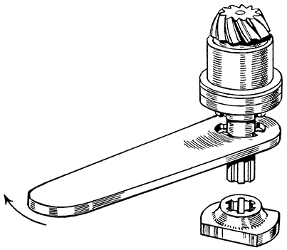
FIG. 42
Vice Tool LET788 shown below the splined end of the bevel pinion shaft
and service Spanner LET789 to be used for unscrewing the lock ring.
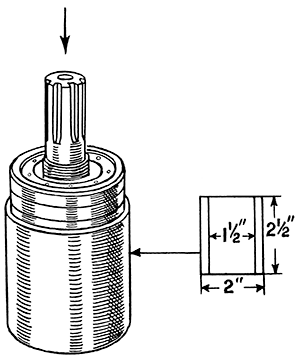
FIG. 43
A suitable Bush for use while pressing out the bevel pinion.
Fit the plain end of the spindle into the Clamping Tool LET790 with the hub-driving teeth close up to the tool. Clamp firmly in a vice, but take care not to distort the spindle by overtightening.
With the cover uppermost (Fig. 44) remove the lock-ring with Tool LET780, unscrewing it anti-clockwise. Remove the assembly from the vice and pull off the clamping tool from the spindle. Tap the spindle out of the cover using the rawhide hammer once more to prevent damage to the threads. A round key prevents the spindle turning in the cover. This will now be free and must be kept for refitting.
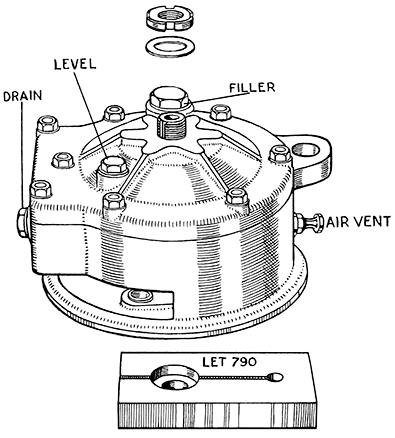
FIG. 44
The Bevel Casing.
The Clamping Tool No. LET790 receives the plain diameter of the
fixed spindle. Place tool in vice to grip spindle while lock ring is removed.
Removal of Crown Wheel Shaft Assembly from Cover.
Heat the cover, preferably by immersion in boiling water. If a flame is used very great care is required not to cause distortion by overheating, and there must be no concentration of the flame at one point.
Expansion of the cover frees the crown wheel shaft ballrace and with the shaft it will come away from the housing in the cover. There are usually packing shims between the ballrace and the cover. These control the meshing of the crown wheel. If the crown wheel is to be refitted the same shims will be needed for refitting. A new crown wheel may require an alteration to the shimming, but in either case keep the shims for use again when reassembling.
Take out the oil seal housing with the oil seal fitted to it, and the fixed spindle plain washer (inner).
Removal of Ballrace from Crown Wheel Shaft.
N.B.—Unless the crown wheel or bolts are to be renewed there is no need to remove it, and it is best left in position. The tightness of the nuts should be checked however and they should be tightened if necessary.
Clamp the crown wheel shaft in the vice. Cover the vice jaws to prevent damage to the ends of the shaft. Lever the ballrace off as far as the vice jaw will allow, unscrew the six self-locking nuts from the crown wheel bolts. Remove the assembly from the vice. Take away the ballrace and crown wheel.
Additional to the bevel pinion oil seal—already mentioned—there are two on the crown wheel shaft. The one behind the crown wheel is only accessible after removal of the crown wheel ballrace from the housing. If there has been leakage of oil into the rear brake this should be renewed at this stage and before the crown wheel shaft and ballrace are refitted.
To renew, press the old one from the separate housing that carries it and press in a new one with the Tool LET787.
The outer oil seal can be prised out of place and a new one can be fitted without any dismantling other than the removal of the rear wheel, so that the replacement can be deferred until the assembly has been completed. It is inserted by using the fitting tool LET963 (Fig. 45).
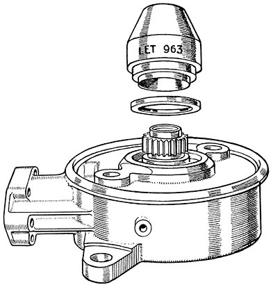
FIG. 45. Using the Special Oil Seal Tool No. LET963 for fitting oil seal to bevel casing.
The tool is used as follows : Lightly grease the sleeve of the tool and slide a new seal on to it. The metal face goes on the tool first so that the seal enters the housing correct way round, i.e., with the sealing edge to¬wards the inside of the bevel casing.
Place the tool and seal over the hub-driving serrations on the crown wheel shaft and enter the seal square with the housing. Keeping it square ; tap the other end gently until the shoulder of the tool comes up against the lip on the casing.
When home, give the tool half a turn, at the same time exerting pressure away from the oil seal and withdraw it.
N.B. - If leakage has been taking place the oil seal collars that run in the seals should be very carefully inspected for scratches. Even apparently minute markings can cause leakage. Polish out any that are noticed with superfine emery cloth working round in the direction that the shaft runs. Do not reduce the diameter any more than is essential to clean up.
Also note that oil that leaks past the seals is caught in a gutter formed in the casting around the brake side seal from which it can drain out clear of the brake, through the drain hole. Make a point of checking that this hole is not restricted or blocked altogether.

