- Details
- Category: F62-1R Service Manual
- Hits: 614
THE FRONT FORK ASSEMBLY
In the event of attention to the fork strut assemblies being required it is easier to remove the strut or struts from the cross members leaving the steering column mounted in the frame. The front wheel and mudguard must be taken out.
Removal of Fork Strut Assembly.
If removing the right hand strut assembly, detach the brake cable clevis and screw out the cable adjuster from the slider.

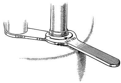
FIG. 37 Service Tool No. LET 783 Fork Lock Ring Spanner.
Support the front of the machine to leave the front wheel clear of the ground. Take off the headlamp cowling by slackening the two headlamp fixing bolts, and taking out the two small pins that are slightly to the rear of them.
Remove two pins securing the headlamp bracket to the fork struts at the bottom in front. Spring the sides out slightly and push it upwards to expose the two castellated lock-rings (Fig. 37). Unscrew the ring from whichever strut it is required to remove, lifting it clear of the threads. Unscrew the hexagon nut at the top (this also holds the handlebar), and remove it; preserving the small lug or bracket from beneath it. Also preserve the bracket from below the lock-ring.
Draw out the strut downwards through the cross members.
Hold the assembly upright to retain the oil and slide off the tubular dust cover. Grasp the spring in one hand and twist the main fork tube (the upper part) anti-clockwise with the other. In a similar manner screw the spring out of the scroll on the top of the slider.
To separate the slider from the main tube assembly hold it in one hand and the tube in the other. Telescope them together and then pull them apart as smartly as possible. Repeat this until the slider bush is forced out of the slider. Empty out the oil from the slider and remove the spring.
The bushes can be removed from the main tube after prising the circlip out of the groove at the bottom end of the tube below the bush.

FIG. 38. Front Suspension System. The Split Bush LET796 is for use
In forcing the Bush on the Fork Leg into position.
This is just a reversal of the dismantling process except that the Service Tool LET796 (Fig. 38) is used to drive in the slider bush. Before putting back the slider over the main tube make certain that the circlip locating the bottom bush is firmly seated in the groove, also pour in 1/8 pint (71 c.c.) of engine oil (S.A.E. 30).
Hold the assembly upright and insert the bottom bush into it. Push down the main tube and enter the slider bush in top of the slider. Rest the whole assembly on a block of wood and fit the split collar LET796 around the fork tube between the bush and spring. Drive the bush home by lifting the assembly off the block and bringing it down again sharply.
Engage the spring in the bottom mounting and, with the fork end lug held in the vice, twist the spring home tightly. Slide the tubular dust cover into place.
If they have both been removed make certain that they are put back on the right sides. The one on the left hand side has a split lug for the spindle and carries a clamp bolt and slotted collar.
Push the assembly up through the hole in the bottom cross member, and as the threaded end emerges place over it first the headlamp cowling fixing bracket followed by the lock-ring. Before the top end is pushed through the handlebar lug fit the top headlamp cowling fixing bracket. Push the strut upwards still further and refit the hexagon nut to it.
Before tightening up the lock-ring and the nut set the strut assemblies so that the fork ends of the sliders point over to the right by about 20°, and also set the bottom fixing brackets in correct alignment for the fitting of the headlamp bracket fixing pins.
When the front mudguard stays and guard are fitted the sliders will be pulled into alignment and the tension on the fork springs keeps the springs firmly in the scrolls.
After tightening the lock-rings slide the headlamp bracket, assembly down over them and put back the two fixing pins. Refit the headlamp cowl.
To hold the lower lamp bracket fixing brackets in alignment whilst the lockrings are tightened it is helpful to get a strip of mild steel about 4-in. long by about 7/16-in. wide and 1/8-in. thick. Drill two holes in it 3½-in. apart and 3/16-in. diameter.
Line up the brackets roughly and bolt the strip to them with the bracket fixing bolts. They will then be held in place whilst the lockrings are tightened.

