- Details
- Category: KSS, KTS Mk II OHC Instruction Book
The Lighting Equipment 6-volt
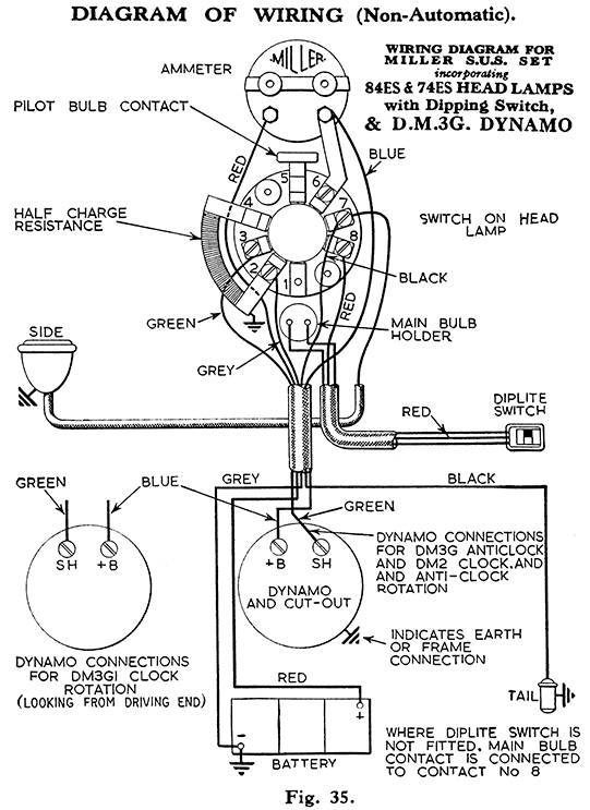
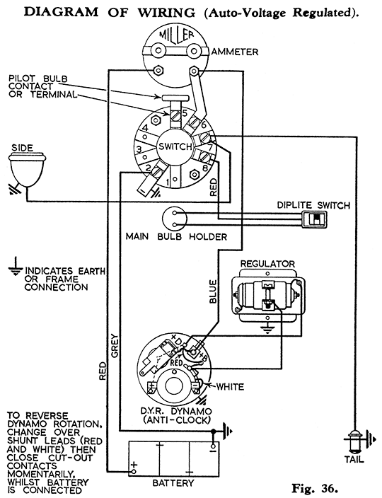
The following instructions apply to all Models, except that the wiring in the headlamp differs slightly. Reference to the respective wiring diagrams will explain fully.
CHARGING.
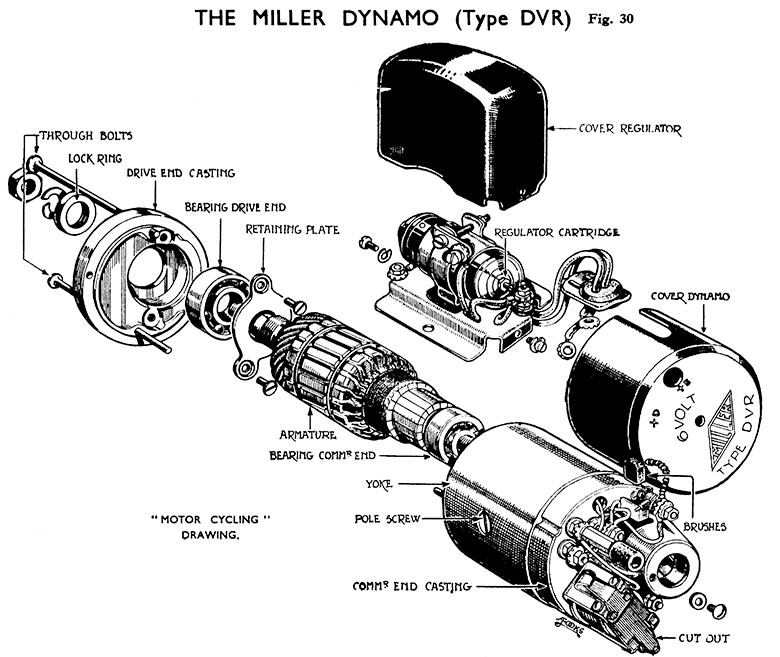
(i) Dynamo. Type, Miller DVR.
(ii) Dynamo - Testing.
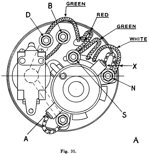
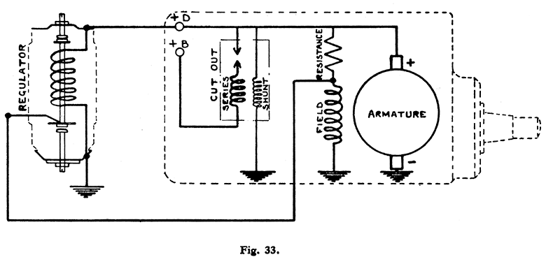
Remove the cover securing screw, then remove cover, this exposes commutator end bracket as Fig. 31. Disconnect the three outside leads (Regulator and Head Lamp) from terminals D.B.S. Clip the negative lead of a good quality moving coil voltmeter, reading from 0-10 volts to a clean earthing point on the dynamo, and clip the positive lead to terminal "B."
Start engine and slowly increase its speed. If no reading is shown on the voltmeter then clip positive lead of voltmeter to terminal "D." If a reading is then shown the cut-out is at fault (try adjusting as instructions). If no reading, the fault is in the dynamo itself. On no account must the engine speed be increased during testing to such an extent that a reading of 8 volts is exceeded. If dynamo and cut-out are in order, re-connect the three leads to terminal D, B and S., and test regulator, para. (viii).
(iii) Dynamo - Removal.
Electrical breakdown of the dynamo is most unusual, and the unit should be tested as described above, Para. B. (ii) before assuming that removal is necessary. Take off belt cover by removing bolt from centre of cover and nut securing cover to primary chain case. Unscrew the dynamo clamping strap bolt about *-in. (do not completely remove bolt). Turn the dynamo in its mounting until the belt is loose, and remove the belt. Disconnect the three dynamo wires as described in Para. B(ii). and remove dynamo complete.
(iv) Dynamo—Dismantling.
Remove belt drive pulley from Armature shaft by taking off the nut and washer and drawing the pulley off the tapered end of the Armature shaft with a " Claw " extractor. Be careful when using the extractor not to damage the thin flanges of the pulley.
Remove brushes " A " and " X " (fig. 31) from their holders. Unscrew and remove the two long bolts securing both end castings of the dynamo yoke. The countersunk heads of these screws can be seen at the driving end.
With the aid of a 3/8-in. diameter metal punch and hammer, tap the armature spindle at the commutator end. As soon as the ball race at the commutator end is clear of the casting, the armature complete with driving end casting, can be withdrawn.
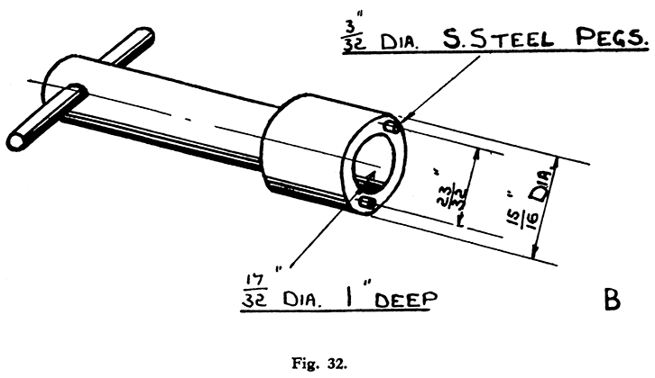
If it is necessary to remove the driving end casting from the armature spindle, first remove the pulley key from the spindle, then unscrew and remove the bearing lock ring, located on the armature shaft just behind the tapered portion. No attempt should be made to slacken this ring by knocking round with a punch. A special pin spanner should be used as shown in Fig. 32. If this spanner cannot be obtained, it can easily be made. The hardened pins are 3/32 inches in diameter, with their centre 23/32 inches apart. The inside diameter of the spanner where it fits around the armature shaft is 17/32 inches.
By rigidly supporting the bearing retaining plate which will be seen inside the driving end casting, the armature spindle may then be pressed out. Care should be taken not to damage the screwed portion of the shaft during this operation, nor should the centre hole be damaged or the shaft distorted in any way.
To remove the commutator end casting from the yoke, first disconnect at D, N and S, the four insulated leads, as soon in Fig. 31 (one each white and red and two green) which pass through the end casting to the field coil. The end casting can then be pulled away from the yoke, care being necessary to ensure that the four leads are not damaged in passing them through the accommodation slots in the end casting.
(v) Dynamo Commutator and Brushes.
Test and Repair. Check that the brushes are clean and move freely in their holders. If there is any stickiness, remove the brush and clean the sides with a cloth moistened with petrol, or by lightly polishing with fine glass paper. Always replace brushes in their original positions. Brushes which have been worn so that they do not bear firmly on the commutator, or which expose the embedded end of the flexible on the running face must be replaced. The commutator must be clean, and free from traces of oil and dirt. When the dynamo has not been removed a dirty or blackened commutator can be cleaned by pressing a fine duster against it while the engine is slowly turned over. If the commutator is very dirty the duster should be moistened with petrol. (If required, the commutator micas should be undercut to a depth of approximately .025-in., but this operation can only be done after the Armature has been removed).
After fitting new brushes, they must be correctly bedded to ensure that they will make good contact with the commutator. To bed the brushes pass a thin strip of very fine glass paper between the commutator and each of the brushes, making sure that the smooth side of the paper rubs on the commutator, then pull the paper backwards and forwards for a few strokes, and then remove the paper. Wipe away any carbon or glass-paper dust after the operation.
Dynamo Field Coil. - Test and Repair.
The resistance of the field winding (red and white leads) should be 4 ohms. +or - .25 ohms, and of the resistance winding (green leads) 7 ohms. +or - .25 ohms. Megger test to earth and megger test between field and resistance windings should be not less than 100,000 ohms. When fitting new field coil, force yoke and pole on to a mandrill about 8-in. long, the diameter tapering from 1.767 inches to 1.773 inches. Grip the exposed end of the mandrill in a vice, and by using a robust screwdriver, the countersunk screw securing the pole shoe to the yoke can be screwed up dead tight. It is important that there should be no air gap between the pole shoe and inner face of the yoke.
Dynamo Armature.—Test and Repair.
The resistance of the Armature Coils measured between two adjacent commutator bars should be .2 ohms +or -.01 ohms. Megger test to earth should be not less than 100,000 ohms.
Dynamo Bearings.—Replacement and Lubrication.
The drive end bearing can be removed from the drive end casting by unscrewing the two small screws securing the bearing retaining plate also the small grub screw on the outside boss. The bearing can then be tapped out. The commutator end bearing can be removed from the armature shaft by using a suitable extractor (it is not a very tight fit on the shaft).
Ball bearings must be carefully packed on assembly with High Melting Point Grease. Grease G.S., should not be used. Subsequent lubrication in service is by removing the round-headed screw retaining the com¬mutator end cover plate and inserting oil in the screw hole, and to the driving end bearing by removing the grub screw on top of the bearing housing, and inserting oil in the screw hole.
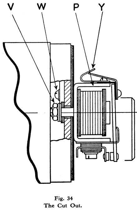
Cut-Out.—Test and Adjust. Fig. 34.
The cut-out "P" is attached to the commutator end casting by one nut "V" and may be removed after disconnecting the lead to the earth retained to the end casting by round headed screw and washer "W," and the lead to the middle of the three terminals "B" Fig. 34.
Resistance of series winding .09 to .1 ohms. Resistance of shunt winding 55 to 56 ohms. Contact clearance 1/32-inches. Contacts should close at approximately 6 volts, when a current from zero to ¼ amp. is being generated, and open when current falls from zero to amp. discharge. The " off " and " on " tension can be adjusted by bending the brass tensioning bracket (Y).
Reverse the procedure in Para. B (iv) bearing in mind the following points :
| a) |
Fit the commutator end casting to the yoke first. |
| b) |
Pass the red lead and the adjacent lead through the triangular slot in the end casting. |
| c) |
Pass the white lead and the adjacent green lead through the long curved slot in the end casting. |
| d) |
Fit the drive end ball bearing to the end casting, fit the assembly over the tapered end of the armature shaft. Replace the drive side bearing lock ring, tighten fully on armature shaft, then gently press the commutator end ball race already on the armature shaft into its housing. |
| e) |
Replace and tighten fully the two long screws securing the end castings to the yoke. |
| f) |
Replace key and belt pulley. |
| g) |
Fit the rubber bush protecting the leads in position in commutator cover band. |
| h) |
Connect wires (interior). Green (through triangular slot) to top terminal " D " (Fig. 31) Red to bottom terminal "S." Green (through long curved slot) to bottom terminal "S." White negative right-hand brush terminal "N." |
| i) |
Connect wires (outside). Black 5 m /m with Red band from regulator to "D" terminal. Black 5 m /m plain from regulator clip to "S" terminal. Black 5 m /m with Blue band from Head lamp (ammeter) to "B" terminal. Replace brushes and fit dynamo to machine, afterwards fitting commutator end cover. |
vii) Regulator Type—Miller CVI.
The regulator provides complete automatic control, so that the dynamo output varies according to the load on the battery, or its state of charge. Normally during daytime running, when the battery is in good condition, the dynamo gives only a trickle charge, so that ammeter readings will seldom exceed 1 or 2 amperes.
If, under normal running conditions, it is found that the battery is continually in a low stage of charge, or is being overcharged, and the test described in para. (ii) has established that the dynamo and cut-out are in order, the regulator may be tested by substitution if a replacement is available. It should be noted that it is quite safe to run the " Miller " dynamo without the regulator cartridge being fitted. When removed, and the dynamo leads left in place, that is, the one with the red identifica¬tion sleeve connected to the base plate, and the other with the green identification sleeve, to the clip bolt, the dynamo gives a reduced output, with a maximum of approx. 3½ amps. It is therefore advisable to fit a replacement regulator as soon as possible.
To test whether the regulator is at fault, disconnect the battery positive lead, and connect a moving-coil voltmeter to the two regulator base terminals (positive and negative), start the engine and run at an equivalent speed of not less than 20 m.p.h. (approx. 1,000 r.p.m.) If the regulator is in correct adjustment the voltmeter reading should be from 7.5 to 7.9 volts.
If the voltmeter reading is below 7.5 volts over regulation is taking place, causing the battery to be continually in a low state of charge. If a spare regulator is not available, a temporary adjustment may be made by screwing out the negative contact screw (which is visible at the conical end of the regulator cartridge), two complete turns. Should the voltmeter reading be over 7.9 volts, which would cause overcharging, a temporary adjustment may be made by screwing out the positive contact screw at the other end not more than ¼ turn.
Note.—These adjustments will not give the correct voltage readings, but will enable the machine to be run with improved results until it is convenient to fit a replacement regulator.
Regulator - Remove and Replace.
The regulator is fitted to the strap which retains the dynamo in position —the cartridge being easily removed after removal of the cover. The pressed steel base and cartridge clip need not be removed unless broken. (vix) Ammeter. Type—Miller /75V.
The Ammeter is retained to the headlamp shell by a metal bridge and two knurled nuts.
With engine stationary, switch on the lights, the ammeter should indicate the equivalent lamp load, upon switching off, the needle should swing back freely to zero. If at fault replace as soon as possible.
Battery. - It is essential to give the battery regular attention, as upon its condition depends the efficiency of the lighting. At least once a month remove the vent plugs from the top of the battery and examine the level of the electrolyte. If necessary. add distilled water to bring the level above the tops of the plates but well short of the bottom of the vent plugs. This operation is best carried out just before commencing a journey when the agitation due to running and the gassing caused by charging will thoroughly mix the solution.
Should the machine be laid up for several months give the battery a small charge from a separate source of electrical energy about once a fortnight in order to obviate any permanent sulphation of the plates. Do not remove the electrolyte from the battery and allow the plates to dry as certain chemical changes take place which result in loss of capacity. It is best to check the specific gravity of the electrolyte by means of a hydrometer as this gives a good indication of the state of charge of the battery.
Specific gravity figures are: -1.285 to 1.300 fully charged, 1.210 half discharged, and 1.150 fully discharged. Never leave the battery in a discharged condition, and unless some long daylight runs are to be made, during which the battery can be charged, remove the battery from the machine and have it charged from an independent supply.
Always see that the connections are clean and tight and to prevent corrosion smear them with vaseline. Loose or dirty battery connections may cause burned out bulbs.


