- Details
- Category: MAC Service Guide (1965)
- Hits: 6298
The Gearbox
Dismantling.*
It is possible to remove all the shafts and gears from the gearbox without dismounting the housing from the frame, but if the layshaft ballrace and sleeve gear ballrace need renewal the housing must be taken out. The gearbox and engine are removed, together as a unit. See page 36.
Drain out all oil by removing the drain plug from the end cover (Fig. 16, page 36). Take out the two ¼-in. B.S.F. bolts from the gearbox cover (above the kickstart bearing) and remove the cover. Hold the gearshaft from turning and unscrew the gearshaft nut which is exposed by the removal of the small cover.
Unless the kickstart spring or ratchet need attention the kickstart bearing should be left in place attached to the gearbox end cover. (For attention to kickstart see page 34.) Tap the gearshaft into the gearbox a little way to free the ballrace, remove the seven ¼-in. B.S.F. cover bolts and pull the cover off the housing. Note the two dowels which may be left in the face of the housing or come away with the cover, and preserve these for refitting. The gear control pedal may be left attached to its spindle.
The layshaft is supported in the kickstart ratchet by a floating bush and this may be left on the end of the layshaft or come away in the ratchet. There is also a hardened steel disc in the ratchet (Fig. 15), this must be carefully retained for refitting. Also remove from the layshaft the layshaft washer fitted up against the ratchet gear.
* 'Light' type boxes Series 11/, are dealt with in exactly the same way as the 'Heavy' types Series 12/ or 14/.
Pull the gearshaft first gear wheel off the gearshaft.
Draw out the two selector fork rods - these are grooved near the ends to provide a means of gripping them. Pull the gearshaft right out towards the clutch side of the machine and pull out the double sliding gear and upper fork, also the layshaft assembly and lower fork.
Special Note. - In all gearboxes that have sleeve gears with more than sixteen gear teeth, that is those that have ' Close ' or ' TT Close ' ratios (fitted to special order) the top gear pick-up dogs overlap the spaces between the gear teeth in all but one position. If the layshaft will not come out of mesh with the sleeve gear with light pressure, turn the sleeve gear round to bring the 'clear' space to the bottom. This applies to all gearboxes with serial number prefixed by the figures 12/.
If the clutch has been removed the sleeve gear will tap through its ballrace into the gearbox and can then be removed. Only the layshaft ballrace and the sleeve gear ballrace, together with the camplate and its attendant mechanism remain in position.
The Operating Mechanism.
Experience has shown that attention is practically never required to this part of the gearbox mechanism and it should not be disturbed needlessly.
Should the camplate be taken off its spindle note that it is mounted on a loose centre-piece - the camplate ratchet plate - and it must be set correctly in relation to this part. Accordingly the two parts are marked and if removed from the ratchet plate the camplate must be fitted with the V mark on it facing the corresponding mark on the ratchet.
After very long use indeed some wear may be found on the steel pegs in the selector forks which engage the operating slots in the camplate. These are renewable separately by driving them out of position and pressing in new ones. No attention whatever is likely to be required to the gear change lever shaft and bearing in the end cover, the rocker shaft bushes, or connecting linkage.
The Gearbox Bearings.
The gearshaft bearing in the end cover will jar out of place after removal of its locating circlip if the cover is heated, and the gearbox housing should be heated in order to free the layshaft ballrace which also will jar out of its housing. To refit or replace heat the housing and cover and tap the bearings into place.
The sleeve gear ballrace which is fitted between two thin steel oil retaining shims is held by a retaining ring threaded into the housing. To reach this ring the back half of the primary chain cover must be removed, and the thrust cup taken away. The thrust cup is held into its seating by a small wire clip retained by two 1/8-in. screws.
The metal at the edge of the hole for the ballrace retaining ring is punched into the notches in the ring for locking purposes. The overlapping metal must be chiselled off carefully to clear the ring.
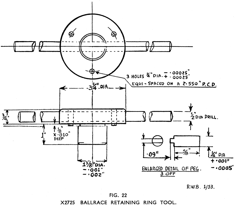
To unscrew the retaining ring use Service Tool No. X2725 (Fig. 22), which will avoid damaging the ring. The oil retaining shim outside the ballrace will lift out and the ballrace can be tapped out after heating the housing around the bearing. The second shim will now come away.
Examine the shims carefully and if in the slightest degree worn or showing any signs of splitting they must be replaced. When refitting the shims and the ballrace — or renewing them — great care must be taken to centralise the shims accurately, otherwise the sleeve gear oil thrower and the distance piece will rub against them and cause wear, eventual failure, and oil leakages.
The ring when finally tightened should be in such a position that one of the grooves at the back of the ring, is at, or near the bottom so that any oil passing the shims and collecting in the recess behind the retaining ring may drain away back into the gearbox through the drilling in the housing. Preferably the ring should tighten up fully with one of the outer slots at or near the top which will ensure that one groove at the back will be near the bottom.
Refit the sleeve gear noting that the oil thrower is in place with its concave side next to the gear teeth.
The bushes in the second and third speed layshaft gears and the low gear bush are easily replaced, but to renew the former the layshaft assembly must be dismantled as described in the next section.
The sleeve gear bush is pegged in position and before attempting to press it out the peg, which passes through the plain ground part of the sleeve gear, must be drilled out. A new sleeve gear bush must be located before pressing in so that the oil holes in the bush will come directly below the oil holes drilled through the gear between the teeth, and after fitting, the bush must be drilled and pegged, and bored out to .001-in. above the gear-shaft diameter. The bush must be bored to ensure concentricity with the ground part of the sleeve gear. Reaming is unsatisfactory.
It is unlikely that the bushes in the low gear, and in the second and third speed layshaft gears will need renewal, but if so they can be pressed out of the gears and new ones pressed in.
After fitting, the low gear bush must be finished bored to .625-in., and the layshaft gear bushes to .8125-in. The limits are plus .0007, minus .0005-in both cases.
Note that current models have two bushes in the low gear. These are pressed in from opposite sides so as to provide bearing flanges at both sides of the gear.
The Layshaft Assembly.
Whilst the layshaft assembly is removed the teeth of the sliding dog, and the corresponding pick up teeth on the second and third gears should be inspected for wear on the edges. The edges must be clean and sharp and if broken away, chipped, or rounded the part must be replaced.
A worn sliding dog can be replaced after removal of either of the end gears—these are splined to the shaft. They may be pressed or levered off the layshaft and will then allow the second and third speed layshaft gears to come off.
When reassembling note that the third speed gear— the larger one — fits next to the ratchet gear, and when pressing them back into place, press them on far enough to locate them without excess end float, but perfectly free to rotate. End float must not exceed .015-in. and is best left at about .005-in.
Refitting the Gears to the Housing.
The layshaft assembly should be held in one hand and the double sliding gear rested in position on the second and third speed sliding gears, noting that the larger gear of the double gear (the one with the internal pick up teeth) faces towards the largest gear on the layshaft (i.e., remote from the ratchet gear).
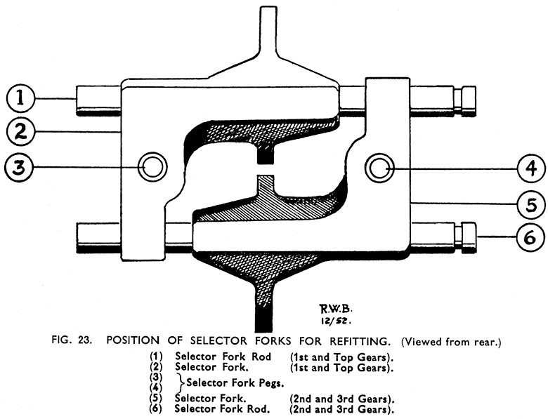
Engage the selector forks in the grooves of the double gear and sliding dog with the forks set so that in the case of the top one the lug carrying the selector fork peg is downwards and the peg between the actual fork and the clutch side of the gearbox (Fig. 23) and the bottom one the other way round.
Place the layshaft assembly, double gear, and forks into the housing, manoeuvring the end of the layshaft into the layshaft ballrace and meshing the layshaft gear with the sleeve gear. Engage the selector fork pegs in the cam tracks in the camplate, and push the fork rods through the selector forks entering their plain ends in the holes in the gearbox housing.
Note. - The lower selector fork rod on all gearboxes 12/ or 14/ is now 1/16 -in. longer overall than originally, so that if the rods are seen to be of different lengths always fit the longer one through the lower fork. The grooved ends fit into the end cover.
Push the gearshaft through the sleeve gear from the clutch side and enter the splines through the splines in the double gear. Refit the gearshaft first gear wheel over the end of the gearshaft, meshing it with the ratchet low gear.
Refitting the End Cover.
Should the kickstart bearing, and kickstart be attached to the cover, make sure before fitting that the kickstart layshaft thrust washer is in place in the kickstart ratchet. If the kickstart bearing is not attached to the cover it may be left for the time being and fitted after the end cover is in place.
Place the layshaft washer over the splines protruding beyond the ratchet low gear, place the kickstart bearing (floating) bush on the layshaft, and, after checking that the end cover ball bearing is in place, with the circlip fitted, put the cover in position using a new gasket on the face joint, and the dowels in position. It will be necessary, as the cover is pushed home to enter the ends of the selector fork rods in their holes in the cover, and the gear-shaft through the end cover ball race. Also the gear control lever must be held up so that the peg at the rear end of the gear change rocker shaft is engaged in the slot in the striking plate assembly. Tighten the holding bolts. Fit and tighten the gearshaft nut against the ballrace and refit the end cover-plate, using a new gasket.
See that the drain plug is fitted.
Refit the kickstart assembly as described on page 36. Note when doing so that the kickstart bearing bush, the layshaft washer, and the layshaft thrust washer are all in their places, and do not use a gasket or paper joint washer between the kickstart bearing and the gearbox end cover.
Refill gearbox with oil and refit the level and filler plugs.


