- Details
- Category: MAC Service Guide (1965)
- Hits: 6962
Primary Chain Cover
Removal of Front Half.
Proceed as described in the preceding section to remove the dynamo belt, but do not take out the dynamo clamp bolt. Remove the front part of the rear chain cover to expose the rear chain driving sprocket. Remove the split cotters from this sprocket and from the shock absorber collar nut. Drain the primary cover.
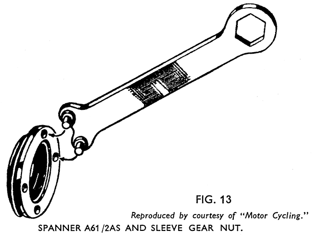
With the rear brake held on; loosen and remove the sprocket nut and the shock absorber collar nut, using spanner A61/2AS for the former and A229 for the latter. Preserve the plain washers which are fitted behind these nuts. The driving pulley, and pulley flange will come off with the collar nut. Remove the shock absorber spring and shock absorber clutch from the engine shaft.
The rear half of the belt cover can be raised over the engine shaft and the cover swung round out of the way of the primary cover.
Unscrew the primary chain cover strap fixing pin (3), Fig. 7, page 21, from the lug on the strap. Free the strap from the cover all round and push it off and over the back half of the cover. Remove the chain case fixing bolt (5) with washer and inner distance piece and pull out the joint mould¬ing.
Remove the cover. Preserve the distance tube fitted between the halves of the cover, and the felt oil seal around the opening for the clutch spring holder.
Removal of Primary Chain.
Fix the sprockets to prevent them turning by mounting a sprag from the bottom of the engine sprocket to the top of the clutch chain wheel. Take off the sleeve gear nut locking plate, held to the sleeve gear nut by a i-in. Whit. screw, and unscrew the sleeve gear nut, using the pegged end of the spanner A61/2AS. It will have to be started by driving it round, using a mallet on the spanner (Fig. 13).
As the chain is endless the engine sprocket and clutch assembly have to be drawn off their respective shafts together. The clutch may have to be levered off to start it by using levers carefully between the clutch back plate and the chain case. If care is taken to hold the clutch front plate and back-plate firmly together the clutch can then be refitted afterwards without it having been separated, unless of course it needs attention. Preserve the three thrust pins from the clutch back plate.
Removal of Rear Half of the Primary Chain Cover.
Having removed the clutch, the clutch thrust bearing is accessible, and the four screws securing the half cover to the gearbox can be taken out after cutting and drawing out the locking wires from the screw heads.
A gasket is fitted between the cover and the gearbox, and an oil seal ring between the cover and crankcase.
Refitting the Rear Half.
Verify that the chain case oil seal is in good order and in place on the crankcase main bearing boss. Stick the gasket - or a new one if needed - to the face of the gearbox with grease, and mount the chain case back half in place. Insert the four fixing screws and tighten fully. Fit new locking wires and twist the ends round securely to lock them. Use two lengths of wire passed through the screws horizontally. Do not wire upper to lower screws as this will interfere with the working of the thrust cup.
Refitting Primary Chain.
Engage top gear to prevent the sleeve gear slipping through its ballrace as the clutch is fitted. Verify the condition of the clutch thrust bearing, grease well, and replace, and see that the sleeve gear distance piece is in place on the sleeve gear and fitted through the thrust bearing.
Take up the clutch assembly, holding the back and front plates firmly together and stick the three thrust pins with grease into the holes in the clutch back plate. These pins are each 3/16-in. dia. x .453-in., and must not be confused with the thrust pins used in the kickstart ratchet - so that if this also has been dismantled the point should be checked.
Hang the chain over the clutch chain wheel, and rest the engine sprocket in the loop. The clutch assembly and engine sprocket with the chain in place have now to be placed on their respective shafts. Care is necessary not to allow the clutch plates to separate, and assistance is desirable for this part of the work.
Refitting the Sleeve Gear Nut.
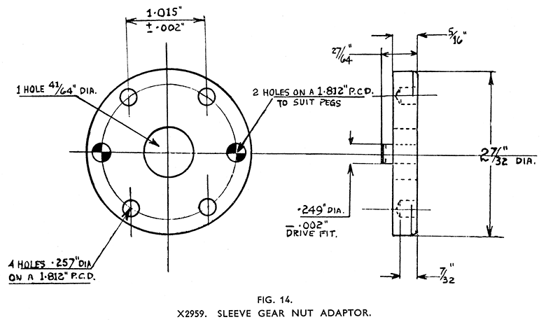
In order easily to refit the sleeve gear nut, which sometimes makes it necessary to compress the clutch spring slightly, the use of Service Tool X2959 sleeve gear nut adaptor (Fig. 14) is advisable. This is fitted over the gearshaft with the pegs engaged in the holes in the sleeve gear nut and the gear shaft nut used to compress the springs enough to start the sleeve gear nut on the thread. The four holes in the adaptor are to enable the peg spanner A61/2AS to be used to turn it.
After starting the sleeve gear nut on the threads, and having fitted the shock absorber clutch, spring, pulley, washer, and shock absorber collar nut sprag the chain and tighten both the sleeve gear nut and the shock absorber collar nut fully, finally driving the spanners round with a mallet. Fit the split-pin to the engine shaft. Readjust the clutch. See page 30.
Refitting Front Half of Primary Chain Cover. (Fig. 7.)
Put the chain case sealing strap in place over the back of the rear half of the primary chain cover. Fit the oil seal felt into its housing inside the cover around the opening for the clutch spring holder.* Fit the front half into place setting it in line with the back half, locating the chain case bolt distance piece over the plunged in edges of the bolt holes in the covers, fit the bolt and washer (5) and tighten up.
Press the joint moulding into place round the edges of the two halves of the cover with the ends at the top, and see that the centre rib fits between the cover faces. Bring the sealing strap over from the back into place over the moulding and tighten the bolt (3).
The reassembly of the dynamo belt cover calls for no special mention. Refill the chain case with oil.
* A new felt must be soaked in oil or molten tallow before fitting.


