- Details
- Category: MAC Service Guide (1965)
- Hits: 14071
The Steering Head And Bearings
Adjustment.
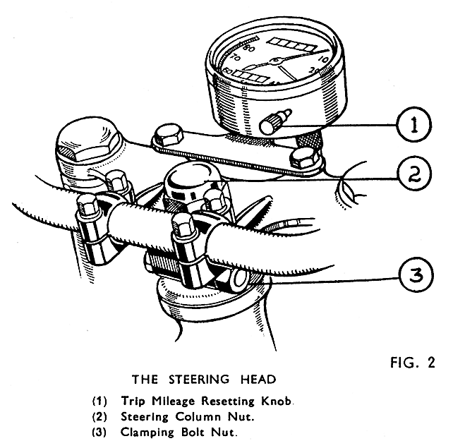
Final adjustment must leave the column quite free without trace of play. To take up play, slack back the top cross member clamp bolt nut (3) and tighten down the column lock-nut (2) until the column begins to bind when checked with the front of the machine supported so that the front tyre clears the ground. Gradually slacken the lock nut until the column is just free, with no trace of play or roughness in working. When correctly adjusted tighten clamp bolt nut (3).
 Fig. 2
Should the column turn jerkily or roughly suspect that the head race cups and cones are pitted, and dismantle the column from the steering head for inspection and if necessary renew the bearings.
Removal of Steering Column. (Fig. 3.)
This will involve removal of the front fork assembly from the steering head, and is easier if the front wheel is removed first, together with the front mudguard and stays.
Disconnect the leads from the battery + terminal. Disconnect the speed-ometer driving flex from the instrument. Remove the handlebar clip bolts and caps and lay the handlebar across the tank top after putting a covering of rag or corrugated paper to protect the tank enamel. Replace the handlebar caps and bolts in the positions from which they were taken. The headlamp may be taken right off after removing the front and reflector and disconnecting all wiring from the switch and lamp, or it may be left connected to the wiring and laid back on the tank, after the front fork cross-member (4) Fig. 3, page 13, has been removed.
Unscrew and lift up both fork damper piston rod adaptors (3) and attach to each rod a length of wire, say 22 S.W.G., and about 18-in. long. These wires are essential to pull up the damper piston rods (24) on reassembling, and unless secured in this way they will drop down into the fork tubes on removal of the adaptors and will be difficult to retrieve.
Loosen the adaptor lock nuts (39) and screw the adaptors right off the rods. Loosen the clamp bolt nut (5) and remove the column lock nut (32). Support the fork underneath and tap the top cross member (4) up and off the column and fork tubes (12). If the headlamp has not been detached from the wiring, remove it from the brackets (37 and 40) and lay it on the tank. See that it is protected from damage.
Take off the dust cover from the top steering head bearing, and lower the fork gently through the steering head of the frame, meanwhile catching any bearing balls which fall out of the races. The upper bearing cone will be left in the top bearing. Store the fork upright to prevent loss of oil.
Renewal of Steering Head Bearings.
Remove the top cone and all the bearing balls and wipe the parts clean. Inspect them carefully for wear or pitting of the ball tracks. To remove the bearing cups from the steering head lug they must be driven out using a suitable steel punch passed through the head and engaged with the edges of the cups. Work from below to remove the top one and from above for the bottom one.
New cups have to be drawn into place quite square with the housings and a convenient way of doing this is to use a ¾-in bolt 8½-in. long, threaded B.S.F. for about 2½-in., and two stout washers to locate in the cups.
The washers should be not less than 3/16-in. (.1875-in.) thick and must be 1 31/32-in. (1.968-in.) diameter recessed on one edge to 1.860-in. diameter to a depth of about 1/16 -in. (.0625-in.) to locate in the cups. (Fig. 4.)
Enter the cups lightly into the housings and with one washer over the bolt, spigot upwards, thread the bolt up through the steering head, fit the other washer, spigot downwards, and thread the nut on to the bolt to hold all parts in place. See that the washers are located in the cups, and the latter quite square, and tighten down the nut until the cups are fully home.
Reassembling the Steering Column.
The bottom steering head cone may be tapped off the column if in need of renewal, and a new one pressed on. Note that the top and bottom cones differ. The top cone is deeper than the bottom one and its inside diameter is smaller.
Stick the bearing balls into the cups with grease, nineteen ¼-in. diameter balls in each cup. Push the steering column up into place through the steering head and hold it up firmly into the bearing.
Push the top cone down over the column followed by the dust cap. See that the top locating cups (10), the buffers (8), and their housings (9) are all in place on the lamp bracket assemblies. Bring the headlamp forward, leading the wiring down between the lamp bracket tubes and the frame head lug and place the top cross member in position, threading the wires from the damper piston rods through the holes. Fit the column lock nut and screw the adaptors on to the damper piston rods, and tighten the locknuts. Remove the wires and tighten down the adaptors.
Readjust the head bearing as previously described and refit the handlebar, tightening the clip bolts evenly.

