- Details
- Category: MAC Owner's Handbook 1955
- Hits: 1823
The Controls
The instinctive and automatic use of the machine which characterises the skilled rider, will not come all at once, but will be acquired gradually.
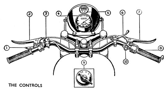
Until the machine can be driven without conscious effort the rider cannot be said to be fully proficient. The controls are illustrated above and described below.
Throttle Control (8). This is controlled by turning the twist-grip on the right-hand end of the handlebar. Move¬ment towards the rider opens the throttle and in most con¬ditions increases the speed of the engine, and (when the gears and clutch are engaged) the speed of the machine. Move¬ment away from the rider closes the throttle. The engine is usually set to idle slowly when hot with the twist-grip fully closed.
Front Brake Lever (7). This is also on the right-hand side, and when gripped and pulled towards the handlebar applies the brake in the front hub.
Clutch Lever (2). This is on the left of the handlebar, and when gripped and pulled towards the handlebar disen¬gages (or frees) the clutch, disconnecting the drive between the engine and the gearbox. It is used on starting and when changing gear and also just before stopping. It must not be used to ease the engine by slipping the clutch instead of changing to a lower gear, be held up in order to free wheel, or to allow the machine to keep stationary (with the engine running) for anything except very short periods.
The Exhaust-Valve Lifter (1). A small lever on the left near the clutch lever. This control raises the exhaust valve from the seating in the cylinder head relieving compression in the cylinder for starting purposes. It is also used to stop the engine when the throttle valve is set to allow the engine to idle when the twist grip is closed.
The Air Control Lever (6). This lever is clipped to the top of the handlebar on the right. Movement towards the rider opens the carburetter air valve. The machine is normally driven with this control full back.
The Horn Push-button (10). Fitted near the front brake lever clip. Press in to sound horn.
The Lighting Switch (9). Fitted into the top of the head¬lamp behind the ammeter. The switch lever has four positions : OFF, CH. H, and L. In either of the first two positions the dynamo will be charging the battery. No lights will be on. In position three " H " one filament of the headlamp will be alight, according to the position of the dipper switch, and the rear lamp and speedometer lights will be on. Fourth position " L " will light the parking bulb in the headlamp and the rear lamp and speedometer light.
All daylight running is done with the switch in " OFF '" or " CH ' position, and at night all riding is done with the switch at " H." The " L " position is used only for parking or occasionally when driving through very well lighted built-up areas.
The Dipper Switch (3). Clipped to the handlebar on the left near the clutch lever clip. Its purpose is to switch the current to one or other of the filaments in the bifocal headlamp bulb. One filament is in centre and gives a direct beam for normal driving. The other which is out of centre, provides a deflected beam for meeting oncoming traffic with¬out dazzling other drivers.
The Rear Brake Pedal. The pedal pad is slightly ahead of the left side footrest and when depressed with the ball of the foot applies the brake in the rear hub.
The Gear Control Pedal. Mounted on the gearbox. The pedal rubber is slightly ahead of the right side footrest. Depression selects a higher gear ratio, raising the lever a lower one. See further description on page 10.
The Kick-start Pedal. Mounted on the gearbox. The footpiece, which folds away when not in use is behind the right side footrest. Illustration page 52.


