- Details
- Category: Rigid Frame MAC Service Manual
- Hits: 3481
Removing and Replacing Front Wheel (Tele forks)
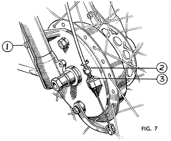
Place a suitable block under the crankcase so that the fork is fully extended and the wheel clear of the ground. Disconnect the brake cable from the cam lever and unscrew the adjuster removing the adjuster and cable from the brake plate. Loosen and take off the spindle nut and washer on the right-hand side. Slacken the clamping bolt in the left-hand fork end, tap out the spindles (which may bring the split collar with it) and the wheel will then come out. The fork sliders will spring over to the right about 20°.
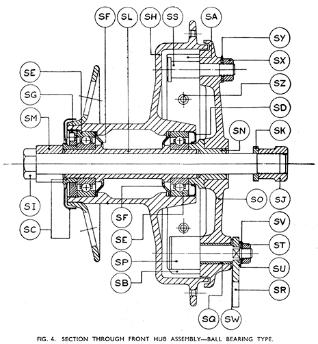
| SA. | Brake Shoes | SJ | Nut for Detachable Spindle. | SR | Lever for Brake Cam. |
| SB. | Brake Shoe Slipper. | SK | Washer for Spindle Nut. | SS | Fulcrum Pin. |
| SC. | Outer Dust Cap and Sleeve. | SL | Hollow Spindle. | ST | Nut for Cam. |
| SD. | Inner Dust Cap. | SM | Split sleeve for spindle | SU | Square Hole Washer for Cam. |
| SE. | Ballraces. | SN | Bearing Clamping Sleeve | SV | Lock Washer |
| SF. | Grease Retainers. | SO | Brake Plate. | SW | Felt Washer for Cam |
| SG. | Ballrace Retaining Ring. | SP | Brake Cam. | SX | Nut for Fulcrum Pin |
| SH. | Front Hub Shell. | SQ | Bush for Brake Cam. | SY | Plain Washer for Fulcrum Pin. |
| SI. | Detachable Spindle. | SZ | Brake Shoe Spring. |
To replace the wheel, push the wheel up into position, being careful to engage the slot in the brake plate over the brake anchor bolt on the fork. Push the spindle through the hollow spindle of the wheel, locating the split collar on the spindle in the split fork end on the left. Fit the spindle washer and nut and tighten the nut fully. Lift the machine off the block and when it is standing on its wheels bounce the fork a few times on the ground. Tighten the clamping bolt on the left-hand fork end and replace the brake cable and re-adjust.
The object of the bouncing explained in the preceding paragraph is to ensure that the sliders of the fork align themselves correctly so that they will work freely.
DISMANTLING FRONT WHEEL BEARINGS - TELESCOPIC FORKS (Fig. 4).
(It is advisable to let a Velocette Service Depot do this job).
Before removing wheel test for ball-bearing wear, Slight freedom is usual. Remove wheel as described in preceding section. Remove brake plate assembly from end of hollow spindle. Obtain a punch made from brass or aluminium bar slightly less than 7/8-in. diameter and about 9-in. long and turned down at one end to just under dia. for a distance of about 2-in. This is necessary to protect the end of the hollow spindle from damage when driving it out. Fit the reduced end of the punch into the end of the hollow spindle on the left-hand side of the hub (remote from the brake drum) and drive out towards the drum. A 1-lb. hammer will usually be sufficiently large to move the hollow spindle satisfactorily. The hollow spindle will drive out of the dust cap on the left-hand side of the hub and carry with it the ballrace from the right and the inner dust cap. This bearing, which will still be in place on the spindle, must be thoroughly cleaned and tested for condition. If any undue slackness is noticed or if the bearing is felt to turn roughly, jerkily, or is stiff, it should be removed by pressing it off and a replacement fitted. If in order, it may be put aside with the spindle until it is needed to re-assemble the hub. The hub ballraces are not adjustable.
Now unscrew the ballrace retaining ring from the left-hand end of the hub, using the peg spanner from the kit. This ring, unlike the corresponding part in the rear hub on machines with rear driven speedometers is a right-hand thread and unscrews anti-clockwise.
The condition of the left-hand bearing can be checked without removal. If satisfactory, pack it with high melting point grease, and re-fit and tighten the retaining ring. Should it be necessary to replace with a new one it must be driven out from the opposite side of the hub and it may be convenient to use the hollow spindle to do it and thus avoid damage to the inner grease retainers. To remove, press the spindle out of the other ballrace and pass it through the hub from the right-hand end of the hub until it is pushed through into the ballrace which it is desired to remove. Fit the punch into the other end of the spindle and drive the ballrace out of the hub. It should be noted that behind each ballrace a steel washer is used to prevent grease working into the hollow barrel of the hub where it is of no use.
Before re-fitting either ballrace therefore, always see that these are in place. (The concave surfaces are always towards the ballraces). Also observe carefully that the ends of the hollow spindle which are reduced to fit the ballraces are not of equal length. The longer ground end must always be fitted into the ballrace on the left of the hub and enters the hub first on re-assembly. This apparently trivial detail is emphasised as it is impossible to assemble the remainder of the hub parts if the spindle is placed the wrong way round. With the ballrace fitted to the shorter reduced end of the spindle and the inner grease retainer in place, push the spindle and bearing into the right-hand end of the hub and with the hammer and punch drive them home. Pack the right-hand ballrace with grease and re-fit the small dust cap. Press the dust cover on to the left-hand end of the hollow spindle, refit the brake assembly when the wheel is ready for re-fitting to machine.
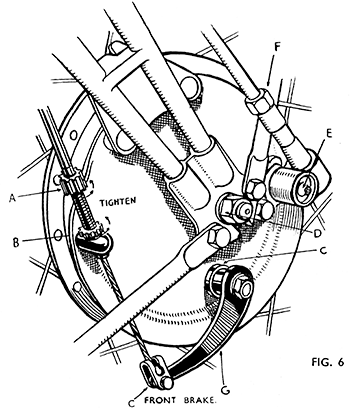
REMOVAL OF FRONT WHEEL - WEBB FORK (Figs. 5 and 6).
Raise the machine on to the rear stand. Loosen the front stand from the mudguard and raise the machine on to the front stand. Pull the brake lever towards the handlebar, grasp the casing of the control cable close to the lever and slip it out of the recess whilst at the same time releasing the lever. Slide the nipple out of the lever, detach all cable clips. Unscrew the hexagon nut at the lower end of the flexible speedometer drive and slip the flex out of engagement with the reduction gearbox. Loosen both spindle nuts, prise the washers out of the recesses in the outside of the fork ends, when the wheel will drop out and can be removed.
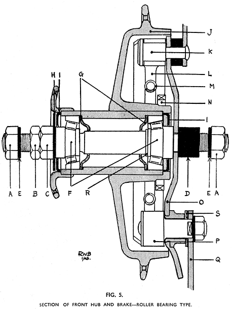
DISMANTLING FRONT WHEEL BEARINGS (Models with Webb Fork Only). (See Fig. 5).
Take off both spindle nuts, and lift out the brake plate and shoes from the brake drum. By using two spanners working against each other, loosen the lock-nut on the left-hand end of the spindle and take this nut and the bearing adjustment nut off the spindle. Take off the dust cap. Using a punch made of brass, copper, or aluminium-alloy drive the spindle through the hub towards the brake drum. In no circumstances must the spindle be driven out from the brake-drum side towards the left. The centre of the roller bearing on the right-hand side will come out with the spindle. The dust cap from the left-hand side of the hub is easily prised out of place and the centre part of the bearing can be taken out. Both bearing cups in the hub can now be repacked with grease.
If the roller bearings have to be renewed due to wear or damage, the old outer bearing rings have to be driven out of the hub in which they are a fairly tight fit. When removing them it is almost impossible to avoid scrapping the grease retaining washers that are inserted between the outer bearing rings and the internal shoulders in the barrel of the hub. If a punch is to hand that will just fit through the barrel of the hub the retainer on one side may be saved, but as one ring and one washer must be taken out before such a punch could be used it is usual simply to drive both rings out of place with an ordinary bar about 3/16-in. diameter and 10-in, long, replacing both grease retainers with new ones on assembly.
Reassembly. (Models with Webb Fork only).
When fitting new roller bearings (which are supplied comprising the centre race, rollers, cage, and outer ring) do not mix up the component parts — see that each centre race with rollers is fitted to run with the ring with which it was supplied.
Place one grease retainer in place — concave side outwards or towards the bearing, press the outer ring of the bearing firmly into the recess in the hub until it is hard up against the grease retainer, which it will then hold in position. Fit the two parts to the other side in a similar manner.
To re-assemble a vice is desirable but not essential. First slide the centre of the brake-side roller bearing up to the shoulder on the right-hand end of the spindle. A small collar or washer will be noticed at the shoulder between the ground part of the spindle and the larger un-machined centre part. The inner ring of the bearing presses against this. Slip the spindle into place from the brake drum side and see that the rollers fit into the bearing outer ring in the hub. The centre part of the bearing must of course be fitted so that the large ends of the taper rollers are outermost. Tap the inner dust cap back into the hub and wipe away any excess grease that may have squeezed out. Put on the flat inside distance washer. Follow up this with the brake plate and shoes, making sure that the small pinion on the reduction gearbox is meshed with the driving gear on the hub. Incidentally, this driving gear is a parallel press fit on to the shoulder of the hub. It is very seldom necessary to replace it, but it can be " prised " out of place using two large spanners packed up (with nuts of suitable thickness) from the back of the brake drum.
Refit the tubular distance piece, spindle-nut and washer, and tighten down the nut to hold the brake plate lightly. Now hold the wheel (brake drum downwards) in a vice by gripping the spindle nut firmly between the jaws. Fit the roller bearing centre into the left-hand bearing ring and tap the inner dust cap into place. Place the flat dust washer in position and tighten down the adjusting nut lightly far enough to allow the wheel to turn freely with only a very slight amount of slackness (about 1/64-in.) noticeable at the wheel rim in all positions. Fit the lock nut and screw it down lightly against the adjuster nut. The setting of the bearings is then near enough for the wheel to be re-fitted to the machine. To dc this, slack off the spindle nut at the brake side enough to allow the spindle to slide up into the fork end and push the wheel up into place. See that the outside washers are snugly fitted into the recesses in the fork ends, the brake plate engaged with the lug on the fork girder, and tighten down both nuts. Check the adjustment. If incorrect, i.e., wheel tight or excessively slack, see next section.
When correctly adjusted connect up the brake cable and adjust the brake (Fig. 6).
| A | Adjuster. |
| B | Lock Nut. |
| C | Felt Washers (keep oily). |
| D | Spindle Nut. |
| E | Greaser for Reduction Gearbox. |
| F | Nut (securing flexible drive). |
| G | Cam Lever. |
Brake Adjustment (Telescopic Fork)
We advise that when dismantling the hub, or in fact any part of the machine, a careful note be made of the positions that the various nuts, washers and other parts occupy before removal. If they are systematically placed in order as taken off and their positions memorised, much time and trouble would be saved and there will not be any of those odd and unaccounted for " left over " parts when the job is done.
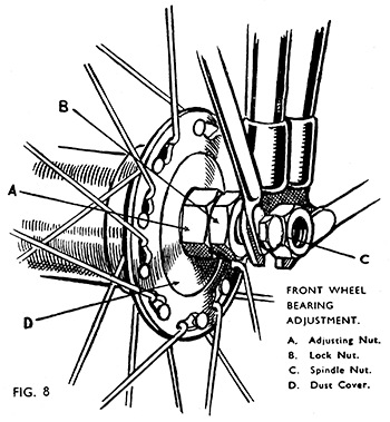
ADJUSTMENT OF FRONT WHEEL BEARINGS (See Fig. 8). (On Machines with Webb Fork only).
Should the wheel be too slack loosen the nearside spindle nut, slack back the lock nut slightly and tighten the adjusting nut until the play is nearly all taken up. Check with the wheel in several positions allowing not more than 1/64-in. play at the wheel rim. Tighten the lock nut, being careful not to shift the adjusting nut. Tighten the spindle nut again and check adjustment once more.
If the bearings are too tight, proceed as above, but slack back the adjuster nut away from the hub. Tap the brake drum over from the off-side, using a wood mallet or a block of wood until play is obtained. Then adjust as described previously.


