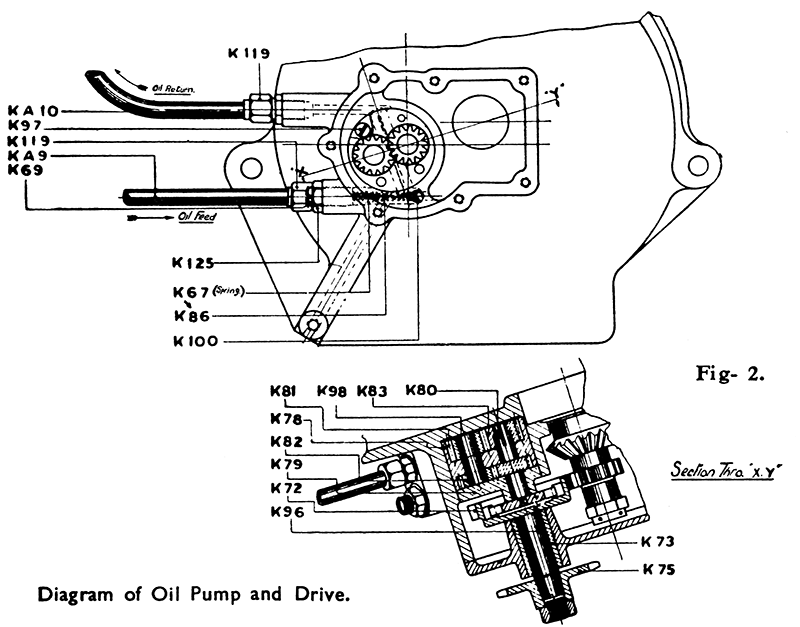
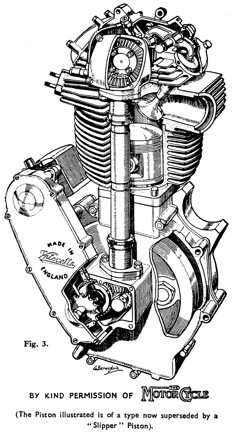
Oil is delivered by gravity to the feed side of a double, gear type oil pump fitted inside, the timing case (behind the magneto chain case). This pump is driven by a coupling engaging with the inside of the magneto driving spindle. When the engine starts the feed side of the pump forces oil through a recess in the oil pump cover into the timing case, vertical shaft cover, and top bevel housing in which pressure is built up.
This pressure forces oil through a ball valve situated in the timing side mainshaft to the big end and through a groove in the camshaft main bearing into the cam chamber. (On engines prior to KSS 8101 oil is led by a pipe from the top bevel housing to a jet above the cams.) A flat is ground on the camshaft so as to overlap the groove in the bearing and form a passage for the oil at every turn of the shaft.
The oil which enters the mainshaft through the ball valve is taken through a passage drilled in the flywheel into a drilling in the crankpin of the big end. The big end is thus fed under pressure and oil is thrown out by the revolving bearing to lubricate the piston, cylinder walls and main bearings, afterwards draining down to the sump whence it is drawn by the return side of the oil pump to the oil tank. On all engines after KSS 8373 a filter is fitted between the sump and return pump. The filter plug is quite accessible and is just above the frame tube and below the magneto chain cover on the right-hand side of the machine. (See also page 16.)
In the upper part of the engine the oil fed into the cam chamber is distributed by the revolving cams to lubricate the rocker ends, rocker spindles and valves.
To prevent leakage of oil down the guides these are now fitted with leather oil retaining washers held in place by steel caps over the ends of the guides. All excess oil drains down the large pipe on the left-hand side of the engine and runs back into the sump.
Excess pressure in the system is relieved by the pressure release valve through which oil is by-passed back to the feed side of the oil pump. This release valve is controlled by an adjustable screw adjacent to the oil feed union on the crankcase at the rear. It is correctly set before delivery of the machine and should not need re-adjustment in the ordinary course of service.
If for any reason it is necessary to re-adjust the pressure release, the adjusting screw should be turned clockwise to increase pressure or anti-clockwise to decrease it. Before the screw can be moved the lock nut must be slackened back anti-clockwise. Any adjustment needed should be made when the oil is thoroughly warm throughout (as after a run) and the screw should not be turned more than half a turn either way at any one time before checking the result of the adjustment - a small movement of the screw often has a big effect on the pressure.
An oil gauge is practically essential for checking purposes if any re-adjustment is made.
IMPORTANT. Before checking the pressure and the return of oil to the tank loosen and remove the lower section of the drain pipe from the Y pipe on the rocker box and arrange to collect any oil from the rocker box in a clean tin. This will ensure that the oil returned to the tank consists only of oil which has passed through the big end and provides a reliable check.
The oil pressure is checked by screwing an oil gauge into the hole provided in the bevel box cover (normally filled by a small hexagon headed plug). On early engines the gauge may be screwed into the hollow bolt which connects the oil pipe to the side of the bevel housing. These hollow bolts are drilled and fitted with a plug.
Normally and with engine oil well warmed up the pressure shown should be about 8 to 10 lbs. per square inch and the return of oil to the tank practically continuous, but in some cases it is possible to work with a slightly lower pressure provided that the return of oil to the tank does not become exceedingly intermittent or very small.
When the system is working correctly there will be both a pressure in the top bevel housing and a good return of oil to the tank - the one is not sufficient without the other.
Oil gauges should be used for checking purposes only and are not intended to be attached permanently to the machine.
The fact that the return is irregular sometimes give rise to enquiry, but it is quite in order. On starting the engine the return may be almost con¬stant for a few moments due to the amount of oil which has drained to the bottom of the crankcase whilst the engine was stationary, and until this surplus is cleared the return flow will exceed normal. During normal running, however, the return is somewhat intermittent, and mixed with bubbles of air due, partly to the fact that the return side of the pump has practically double the capacity of the feed side, and partly to variations in, the amount of oil suspended in the crankcase due to engine speed. For example, upon sudden acceleration the return flow may cease for a time, but will of course resume at a greater rate upon the engine being slowed down.


